Back to Smart Light Categories Page
The Smart Light hardware is capable of communicating to devices using several protocols. Through these protocols the light can be set directly and modes can be triggered. The following protocols can be used with Smart Light:
- RS232
- TCP/IP
- USB (libusb-1.0)
- 24V 8 bit I/O
How to use these protocols to trigger modes and direct set the light is explained in the following sections.
RS232 Protocols
The RS232 protocol for triggering a modes and direct setting the light is much like the other RS232 protocols written by Caron Engineering. Each packet requires a start of packet, mode command, and end an end of packet. The start of packet and end of packet are built from the single character delimiter configured in the recipe file.
The RS232 protocol is currently uni-directional (Only receives data). The serial strings are in ASCII format and must have the following format when sending a command to the system:
(Delimiter)(Delimiter)(Delimiter)(Delimiter)(Delimiter)(Command Letter)(Param1)(Param2)...(ParamX)(Delimiter)(Delimiter)
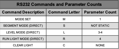
All available command letters are shown in the table below:
Mode Set
The mode set command allows changing the light with respect to the configured modes within the recipe. The mode set command lay- out is as follows:
(Delimiter)(Delimiter)(Delimiter)(Delimiter)(Delimiter)(M)(Mode#) (Delimiter)(Delimiter)
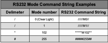
A table of examples is shown below:
Segment Mode (Direct)
The segment mode direct command allows changing the light to segment mode directly. The segment mode command layout is as follows:
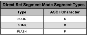
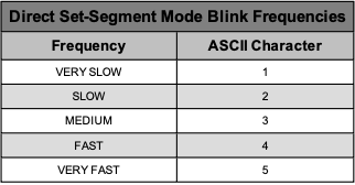
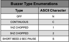
(Delimiter)(Delimiter)(Delimiter)(Delimiter)(Delimiter)(S)(Segment Count)(Segment 1 Color)(Segment 1 Type)(Segment 2 Color)(Seg- ment 2 Type)...(Segment X Color)(Segment X Type)(Blink Frequency)(Buzzer Type)(Delimiter)(Delimiter)
The amount of parameters vary with respect to the segment count. If the segment count is only equal to 1, then only 1 segment color and 1 segment type should be defined. For example, if the segment count is set to 2, the following structure should be used:
(Delimiter)(Delimiter)(Delimiter)(Delimiter)(Delimiter)(S)(Segment Count)(Segment 1 Color)(Segment 1 Type)(Segment 2 Color)(Seg- ment 2 Type)(Blink Frequency)(Buzzer Type)(Delimiter)(Delimiter)
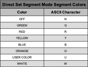
The segment colors are represented as a single ascii character.
Level Mode (Direct)
The level mode direct command allows changing the light to level mode directly. The level mode command layout is as follows:
(Delimiter)(Delimiter)(Delimiter)(Delimiter)(Delimiter)(L)(Level Type)(Level Color)(Level Light Count Digit 1)(Level Light Count Digit 2)(Buzzer Type)(Delimiter)(Delimiter)
The light color is a 2 digit number (0-20 lights). If the light count is less than 20, then a leading 0 character is required before the single digit number to keep the ascii representation as 2 characters.
The level types are represented as a single ascii character displays all available level types:
Run Light (Direct)
The run light mode direct command allows changing the light to run light mode directly. The run light mode command layout is as follows:
(Delimiter)(Delimiter)(Delimiter)(Delimiter)(Delimiter)(R)(Run Segment Count)(Run Color)(Back Color)(Run Speed)(Buzzer Type) (Delimiter)(Delimiter)
The run speeds are represented as a single ascii character.
Temporary User Color
The temporary user color command is represented as 3 separate hex values for the complete RGB spectrum. Each hex value can be from a value from 0-255 in hex (00 to FF). A table of examples is shown below:
Clear Light
This command is the same as sending a mode set with a mode number of 0.
