Back to Detect-IT Categories Page
DTect-IT supports several sensors for use with analyses. Each sensor available from Caron Engineering is documented in this chapter. For more information on sensor capabilities and specifications please contact Caron Engineering. The following wired sensors are available with DTect-IT:
- Vibration Sensor
- Analog Sensor
- Strain Sensor
- Audio Sensor
- Ethernet/USB Power Sensor
- WMRP
- Digilog Probe
Vibration Sensor
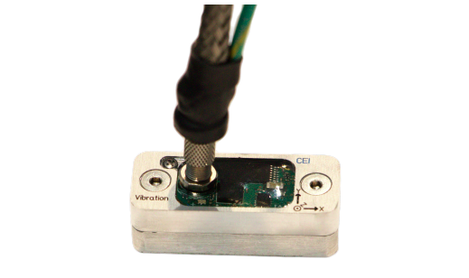
The vibration sensor shipped with DTect-IT has several different data channels that can be read. This includes:
- Vibration
- Acceleration X Axis
- Acceleration Y Axis
- Acceleration Z Axis
- Acceleration Vector
- Temperature
The following specifications are for Vibration:
- Dynamic Range: -800g to +800g
- Sensitivity: 50mg (approximation)
- Frequency Response: 5 Hz to 32.5 kHz at 64 ksps
- Number of Axes: 1 axis- Z
- Vibration Sensor Survival: 10,000g shock
The following specifications are for Acceleration:
- Dynamic Range: -16g to +16g
- Sensitivity: 3200sps/16g - 35mg/LSB
- Frequency Response: 0Hz to 1600Hz at 3200sps
- Number of Axes: 3 axes- X, Y, Z
- Accelerometer Sensor Survival: 10,000g shock
The device is pictured below:
Vibration Sensor Wizard
The Vibration Sensor wizard eases the setup of a Vibration sensor by guiding the user through the settings step by step. Press the Sensor Settings button in the general settings to display previously created sensors. To start the Vibration sensor wizard, press Create in the sensor ribbon and select Vibration. Perform the following steps in the wizard to create the sensor:
- Press Begin.
- DTect-IT queries the connected sensors.
- Once DTect-IT finds a valid sensor, the sensor will blink white and green. If this is the correct sensor, press correct sensor. if the sensor is incorrect, press incorrect sensor and DTect-IT will re-query the sensors excluding the previous sensors.
- Enter a name for the sensor and Press Finish.
After finishing creating the sensor, the sensor will be available in the sensor menu and to analyses.
Note: DTect-IT cannot create two sensors with the same serial number.
Vibration Sensor Settings
The Vibration Sensor Setting menu displays the name of the sensor and the sensor type. The sensor name can be changed by clicking in the field. The Vibration Sensor settings menu has the following tabs:
- Sensor Tab
- Hardware Tab
Sensor Tab
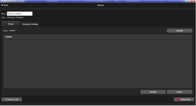
In the Sensor tab, the sensor serial number is displayed and a new sensor can be assigned. This feature is useful for replacing a broken sensor with a new one. By replacing the sensor in the sensor settings, the need to update all analyses using the sensor is eliminated. Press the Identify button to activate the LED on the sensor. The LED will briefly flash white and green.
Replacing a Sensor
Replace the sensor by performing the following steps:
- Press the Refresh button to query the available connected sensors.
- Press the sensor from the list to replace the current sensor.
- Press Select.
Hardware Tab
The Hardware tab displays various diagnostic information about the vibration sensor. The following information is displayed:
- Vibration Channel Maximum
- Vibration Channel Minimum
- Vibration Channel Offset
- Vibration Channel Resolution
- Vibration Channel Scale
- Vibration Channel Unit Type
Analog Sensor
The analog sensor compatible with DTect-IT is a four channel, USB bus powered sensor with optical isolation and input protection. The sensor has the following specifications:
- Resolution: 16 bit
- Sample Rate: 16 ksps
Each channel is configurable within DTect-IT to various input and output modes. Each channel can be set to the following input modes:
- Voltage Mode- This mode has a range of -10V to +10V with the following options:
- ± 10 V
- ± 5 V
- ± 2.5 V
- 0-10 V
- 0-5 V
- Current Mode- This mode has a range of ± 25 mA.
Current Mode
Any device that can output a 4 to 20 mA analog current signal can be attached to the analog sensor and utilized by DTect-IT. This type of output is common in pressure and coolant sensors. DTect-IT receives the signal through the analog sensor and transforms the varying current based on the programmed settings of the analog sensor. DTect-IT correlates the 4 to 20 mA signal to a programmed range of data to be utilized by analyses.
For example, if using the analog sensor to read a current signal from a temperature sensor rated for -40°C to 85°C, the range of current that is associated with the range of temperature that needs to be monitored needs to be programmed in the Analog Channels tab. The low range of the current (4 mA) could be associated with -20 °C and the high range (20 mA) could be associated with 40 °C. As the current signal varies, the data output from DTect-IT would range from -20 to 40 °C.
Analog Sensor Wizard
The Analog Sensor wizard eases the setup of a Analog sensor by guiding the user through the settings step by step. Press the Sensor Settings button in the general settings to display previously created sensors. To start the Analog sensor wizard, press Create in the sensor ribbon and select Analog. Perform the following steps in the wizard to create the sensor:
- Press Begin.
- DTect-IT queries the connected sensors.
- Once DTect-IT finds a valid sensor, the sensor will blink white and green. If this is the correct sensor, press correct sensor. If the sensor is incorrect, press incorrect sensor and DTect-IT will re-query the sensors excluding the previous sensors.
- Enter a name for the sensor and Press Finish.
Analog sensors require the channels that will be used to be configured. After finishing creating the sensor, the sensor will be available in the sensor menu and to analyses.
Note: DTect-IT cannot create two sensors with the same serial number.
Analog Sensor Settings
The Analog Sensor Setting menu displays the name of the sensor and the sensor type. The sensor name can be changed by clicking in the field. The Analog Sensor settings menu has the following tabs:
- Sensor Tab
- Hardware Tab
- Analog Channels Tab
Sensor Tab
In the Sensor tab, the sensor serial number is displayed and a new sensor can be assigned. This feature is useful for replacing a broken sensor with a new one. By replacing the sensor in the sensor settings, the need to update all analyses using the sensor is eliminated. Press the Identify button to activate the LED on the sensor. The LED will briefly flash white and green
Replacing a Sensor
Replace the sensor by performing the following steps:
- Press the Refresh button to query the available connected sensors.
- Press the sensor from the list to replace the current sensor.
- Press Select
Hardware Tab
The Hardware tab displays various diagnostic information about each channel on the analog sensor. The following information is displayed for each channel:
- Channel enabled or disabled
- Mode
- Channel Name
- Channel offset
- Channel Scale
- Unit Type
Analog Channels Tab
In the Analog Channels tab, parameters can be set for each analog channel available in the sensor. To change parameters for a specific channel, select the channel from the channel drop-down menu.The following parameters can be set for each channel in the analog sensor:
- Enabled: Enables or disables the selected channel
- Name: Name the selected channel by clicking in this field
- Mode: Choose the analog mode for the channel. The following modes are available:
- -10 to +10 V
- -5 to +5 V
- -2.5 to +2.5 V
- 0 to +10 V
- 0 to +5 V
- -25 to +25 mA
- Range: Set the range of the converted data from the analog output.
- Convert to: Use this drop-down menu to select the data type the voltage signal needs to be converted to. The following options are available:
- Raw Data
- Temperature
- Acceleration
- Current
- Voltage
- Pressure
- Power
- Displacement
Strain Sensor
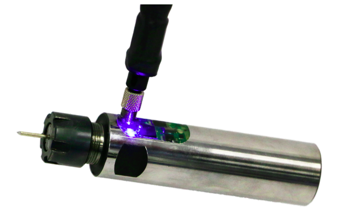
The strain sensor is designed for embedding into parts that are subject to load in a machine. The sensor senses the strain (material deflection) in the part and streams the data back to DTect-IT. Changes in the load on the part result in a signal from a strain gage located under the strain USB device. If a strain gage needs to be installed, Caron Engineering will have to install the sensor in the desired tool. For more information please contact customer service at ceisupport@caroneng.com. The strain sensor has following specifications:
- Voltage Excitation: 2.5V precision reference
- Dynamic Range: to 2.5V differential, 1.25V nominal
- Sensitivity: 3e-7V differential
- Frequency Response: 0 Hz to 32 kHz at 64 ksps , 0 to 16kHz at 32 ksps. (Chosen upon purchase)
- Sensor Survival: 10,000g shock
- Temperature Sensor: -40 to 100°C NTC thermistor
Strain Sensor Wizard
The Strain Sensor wizard eases the setup of a Strain sensor by guiding the user through the settings step by step. Press the Sensor Settings button in the general settings to display previously created sensors. To start the Strain sensor wizard, press Create in the sensor ribbon and select Strain. Perform the following steps in the wizard to create the sensor:
- Press Begin.
- DTect-IT queries the connected sensors.
- Once DTect-IT finds a valid sensor, the sensor will blink white and green. If this is the correct sensor, press correct sensor. If the sensor is incorrect, press incorrect sensor and DTect-IT will re-query the sensors excluding the previous sensors.
- Enter a name for the sensor and Press Finish.
After finishing creating the sensor, the sensor will be available in the sensor menu and to analyses.
Note: DTect-IT cannot create two sensors with the same serial number.
Strain Sensor Settings
The Strain Sensor Setting menu displays the name of the sensor and the sensor type. The sensor name can be changed by clicking in the field. The Strain Sensor settings menu has the following tabs:
- Sensor Tab
- Hardware Tab
Sensor Tab
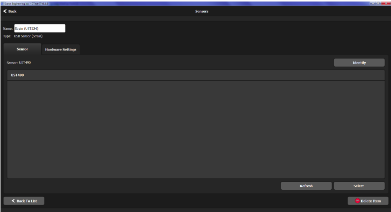
In the Sensor tab, the sensor serial number is displayed and a new sensor can be assigned. This feature is useful for replacing a broken sensor with a new one. By replacing the sensor in the sensor settings, the need to update all analyses using the sensor is eliminated. Press the Identify button to activate the LED on the sensor. The LED will briefly flash white and green.
Replacing a Sensor
Replace the sensor by performing the following steps:
- Press the Refresh button to query the available connected sensors.
- Press the sensor from the list to replace the current sensor.
- Press Select.
Hardware Tab
The Hardware tab displays various diagnostic information about the strain sensor. The following information is displayed:
- Maximum Bridge Resistance
- Minimum Bridge Resistance
- Nominal Bridge Resistance
- Strain Channel Maximum
- Strain Channel Minimum
- Strain Channel Name
- Strain Channel Offset
- Strain Channel Resolution
- Strain Channel Scale
- Strain Channel Unit Type
Audio Sensor
DTect-IT can utilize any audio playback device as an audio sensor to be utilized by analyses. Audio sensors can be used with all analyses except for Bearing Analysis.
Audio Sensor Wizard
The Audio Sensor wizard eases the setup of a Audio sensor by guiding the user through the settings step by step. Press the Sensor Settings button in the general settings to display previously created sensors. To start the Audio sensor wizard, press Create in the sensor ribbon and select Audio. Perform the following steps in the wizard to create the sensor:
- Press Begin.
- DTect-IT queries the connected sensors.
- Once DTect-IT finds a valid sensor, the sensor will blink white and green. If this is the correct sensor, press correct sensor. If the sensor is incorrect, press incorrect sensor and DTect-IT will re-query the sensors excluding the previous sensors.
- Enter a name for the sensor and Press Finish. After finishing creating the sensor, the sensor will be available in the sensor menu and to analyses.
Note: DTect-IT cannot create two sensors with the same serial number.
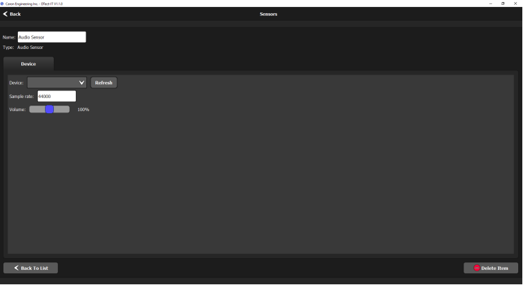
Audio Sensor Sensor Settings
The Audio Sensor Setting menu displays the name of the sensor and the sensor type. The sensor name can be changed by clicking in the field. The Audio Sensor settings menu has the following tabs:
- Device Tab
Device Tab
The following parameters can be set in the Device tab:
- Device: DTect-IT reads all compatible devices connected and lists the devices in a drop down menu.
- Sample Rate: Set the sample rate of the device. This is the number of data points the device processes per second.
- Volume: Adjusts the volume level of the device to allow more control of the signal DTect-IT processes.
Ethernet/USB Power Sensor
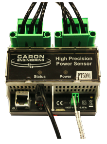
DTect-IT can communicate with power sensors over Ethernet or USB. The following are specifications for available CEI power sensors:
High Precision Power Sensor: Full specs below.
- Input Voltage: 10-30VDC 50/60hz, 1A
- 3-Phase Voltage: 0-600V RMS
- 3-Phase Amperage: 0-35A
- Resolution: 24 Bit
- Response Time: 1mS
- Size: 4.2” x 2.3” x 3.5” (107mm x 60mm x 89mm)
- Weight: .52 LBS (238G)
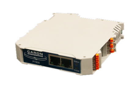
PT800: Full specs below:
- Input Voltage: 10-27VDC 50/60hz, .4-.15A
- 3-Phase Voltage: 0-600V RMS
- 3-Phase Amperage: 0-800A
- Resolution: 24 Bit
- Response Time: 1mS
- Size: .87” x 4.4” x 3.8” (22mm x 491mm x 97mm)
- Weight: .24 LBS (110G)
Power Sensor Wizard
The Power Sensor wizard eases the setup of a Power sensor by guiding the user through the settings step by step. Press the Sensor Settings button in the general settings to display previously created sensors. To start the Power sensor wizard, press Create in the sensor ribbon and select Ethernet/USB Power. Perform the following steps in the wizard to create the sensor:
- Press Begin.
- DTect-IT queries the connected sensors.
- Once DTect-IT finds a valid sensor, the sensor will blink white and green. If this is the correct sensor, press correct sensor. If the sensor is incorrect, press incorrect sensor and DTect-IT will re-query the sensors excluding the previous sensors.
- Enter a name for the sensor and Press Finish. After finishing creating the sensor, the sensor will be available in the sensor menu and to analyses.
Note: DTect-IT cannot create two sensors with the same serial number.
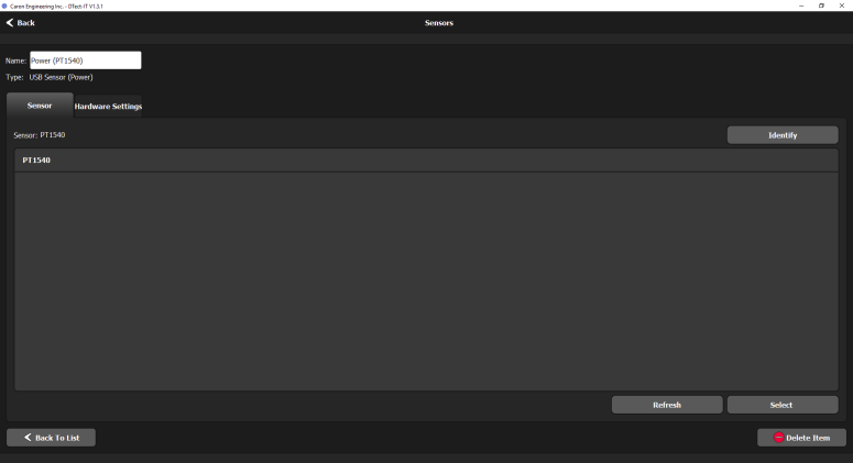
Power Sensor Settings
The Power Sensor Setting menu displays the name of the sensor and the sensor type. The sensor name can be changed by clicking in the field. The Power Sensor settings menu has the following tabs:
- Sensor Tab
- Hardware Tab
Sensor Tab
In the Sensor tab, the sensor serial number is displayed and a new sensor can be assigned. This feature is useful for replacing a broken sensor with a new one. By replacing the sensor in the sensor settings, the need to update all analyses using the sensor is eliminated. Press the Identify button to activate the LED on the sensor. The LED will briefly flash white and green.
Replacing a Sensor
Replace the sensor by performing the following steps:
- Press the Refresh button to query the available connected sensors.
- Press the sensor from the list to replace the current sensor.
- Press Select.
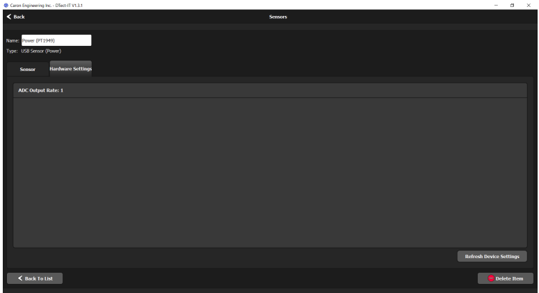
Hardware Tab
The Hardware tab displays various diagnostic information about sensor.
- ADC Output Rate
WMRP
DTect-IT can utilize Caron Engineering's WMRP (Wireless Module Receiver Plus) device to allow communication between DTect-IT and any Caron Engineering provided coax sensor. The device is powered via a USB-B connection and provides one coax connection for a sensor. The following CEI coax sensors are supported:
Coax Vibration Sensor: Full specs below.
- OMNIDIRECTIONAL VIBRATION SURFACE WAVE SENSOR
- Mems sensor (Micro-Elecro-Mechanical-Systems)
- Maximum sampling rate of 41.667 ksps
- Bandwidth of 100Hz-20kHz
- 24 bit resolution o Low signal to noise ratio
- TRI-AXIS SERVO ACCELEROMETER SENSOR o 32g dynamic range
- Maximum sampling rate of 25.6 ksps
- Sensitivity of 1 milli-g
- Bandwidth of 0-6kHz at +/- 3dB, 0-12kHz +/- 5dB
- TEMPERATURE SENSOR
- Digital temperature sensor
- Temperature range from -40C to 85C
WMRP Wizard
The WMRP Radio wizard eases the setup of a WMRP radio by guiding the user through the settings step by step. Press the Sensor Settings button in the general settings to display previously created sensors. To start the WMRP sensor wizard, press Create in the sensor ribbon and select WMRP.
Perform the following steps in the wizard to create the radio:
- Press Begin.
- DTect-IT queries the connected radios.
- Once DTect-IT finds a valid radio, the radio will blink white and green. If this is the correct radio, press correct radio. If the radio is incorrect, press incorrect radio and DTect-IT will re-query the radios excluding the previous radios.
- Indicate if wireless power is being used or not. Note: Using wireless power is a specific use case, contact Caron Engineering for more information.
- If wireless power is being used, continue to step 5.
- If wireless power is not being used continue to step 6.
- Select a power transmitter to use with the sensor and press Continue.
- Press Scan For Devices to scan for remote devices
- Once DTect-IT finds a valid radio or transmitter, the radio or transmitter will blink white and green. If this is the correct radio or transmitter, press correct radio or transmitter. If the radio or transmitter is incorrect, press incorrect radio or transmitter and DTect-IT will re-query the radio or transmitter excluding the previous radio or transmitter.
- Enter a name for the WMRP and Press Finish. After finishing creating the sensor, the sensor will be available in the sensor menu and to analyses.
Note: DTect-IT cannot create two sensors with the same serial number.
WMRP Sensor Settings
The WMRP Sensor Setting menu displays the name of the sensor and the sensor type. The sensor name can be changed by clicking in the field. The WMRP Sensor settings menu has the following tabs:
- USB Radio Tab
- Hardware Settings Tab
- Channels Tab
- Wireless Remote
- Wireless Power
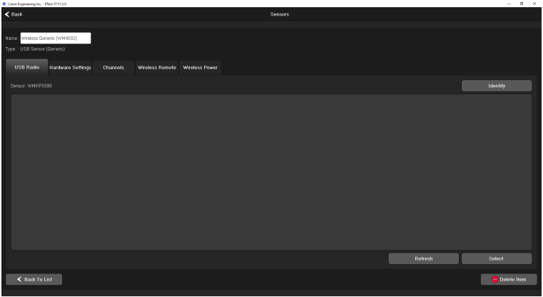
USB Radio Tab
In the USB Radio tab, the WMRP serial number is displayed, and a new WMRP unit can be assigned. This feature is useful for replacing a broken WMRP with a new one. By replacing the WMRP in the settings, the need to update all analyses using the WMRP is eliminated.
Press the Identify button to activate the LED on the sensor. The LED will briefly flash white and green.
Pressing the Refresh button populates a list WMRP's connected to the system.
Replacing a WMRP
Replace the WMRP by performing the following steps:
- Press the Refresh button to query the available connected sensors.
- Press the WMRP from the list to replace the current radio.
- Press Select.
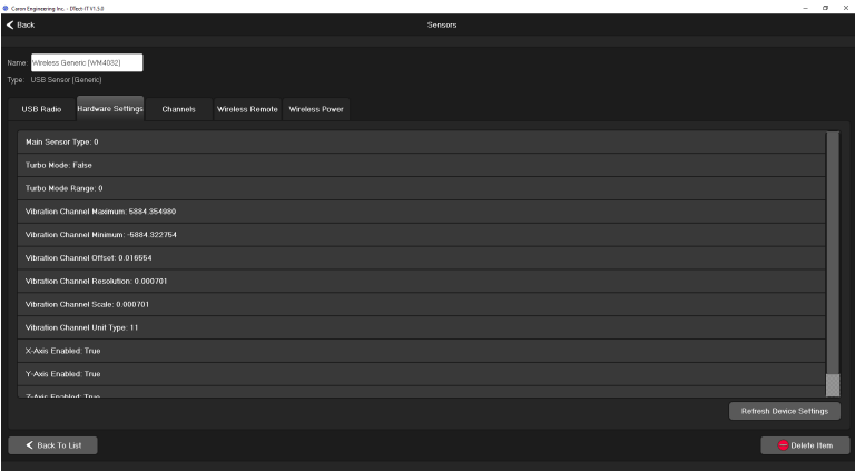
Hardware Settings Tab
The Hardware tab displays various diagnostic information about the sensor attached to the WMRP unit. The information displayed on this tab will vary based on the sensor connected to the WMRP unit.
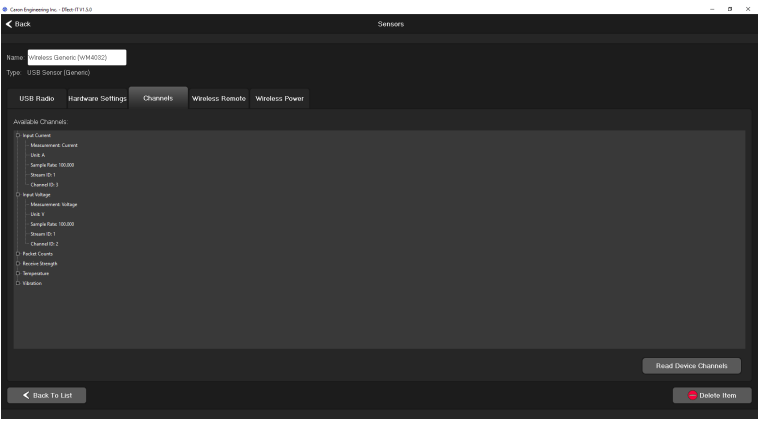
Channels Tab
The Channels tab displays the internal device channels for the WMRP unit. This tab is primarily used for diagnostics. Use the Read Device Channels button to refresh the list of device channels.
Wireless Remote Tab
The Wireless Remote tab displays a list of connected WMRP units. This tab is primarily used for diagnostic purposes. Pressing the identify button for a selected device activates the devices status LED for easy identification of hardware.
Wireless Power Tab
The wireless power tab provides access to the wireless power calibration tool. Wireless power is a specific use case, and users should contact their system integrator for additional information.
Digilog Probe
DTect-IT is capable of communicating with various Digilog probes via an RS232 port.
Digilog Probe Sensor Wizard
The wizard eases the setup of a Digilog probe by guiding the user through the settings step by step. Press the Sensor Settings button in the general settings to display previously created sensors. To start the wizard, press Create in the sensor ribbon and select Digilog Probe. Perform the following steps in the wizard to create the Digilog probe:
- Press Begin.
- Select the RS232 Port for the Digilog probe connection
- Enter a name for the probe and press Finish.
After creating the probe, it will be available in the sensor menu and to analyses.
Digilog Probe Sensor Settings
The Digilog Probe setting menu displays the name of the probe. The probe name can be changed by clicking in the field. The Digilog Probe Sensor settings menu has the following tabs:
- Connection Tab
- Calibration Tab
Connection Tab
The Connection tab allows the selection of the RS232 port used for communication with the Digilog probe. Pressing the Refresh button, refreshes the list of RS232 communication ports available
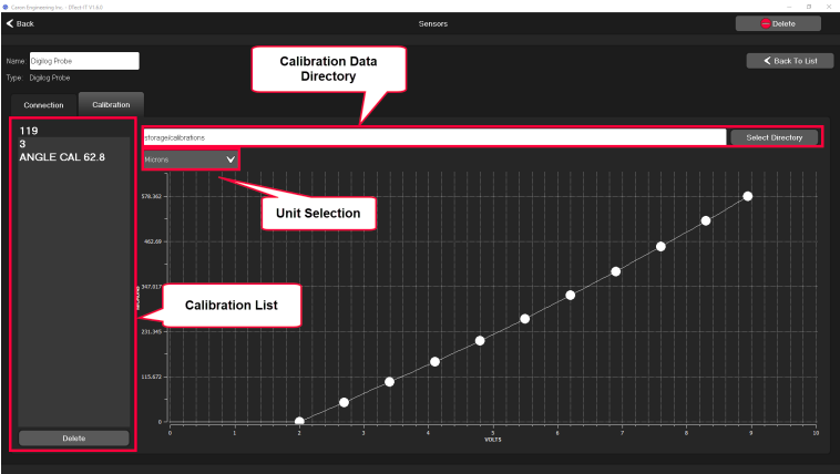
Calibration Tab
The Calibration tab allows Digilog probe calibration data to be viewed. Press the Select Directory button to select the file location of the calibration data and populate the list of calibrations on the left side of the window. Selecting a calibration from the list displays the calibration data on the graph. The data is viewable in Microns or Micro-inches. Additionally, calibration data can be deleted from the list using the Delete button.
