AutoComp supports many CNC interfaces. Each interface requires different configuration parameters. Begin the configuration process by using the Select Compensation Source Machine window to select the CNC interface
"Brother Control"
The CEI Brother server resides on the same PC as AutoComp. This server must be installed and configured separately
First select and configure the Brother CNC interface in AutoComp, before configuring the CEI Brother server.
Note: If an offset cannot be written, then a retry message will be displayed. AutoComp will continue to retry until success, or until the next gage cycle is sent. If the latter, the dimension will be in an error state.
Select and Configure the CEI Brother CNC Interface
When selecting ACSource_Brother to configure, the following window is displayed:
- In the CEI Brother Server IP Address and CNC Server IP Port fields, enter the server IP and port.
- CNC IP should be same as AutoComp PC, but can run on remote PC.
- Port = 11000.
- PageTableCount of CNC is the count of offset and variable page tables of the target CNC. Page tables are selected in each dimension of a routine in the Routine Editor's Path/Tur- ret selection. Enter the number.
- Press Apply.
Now that the CNC interface is configured, the CEI_BrotherServer can be configured.
CEI_BrotherServer Configuration
To configure the CEI Brother server:
- Click on the blue CEI icon in the system tray.
- Select Configure.
- In the window that appears:
- Local Port should not be changed.
- CNC IP as set on control.
- CNC Port = 10000.
- Above information excerpted from CEI_Brother server documentation.
- Press Accept.
ACSource_Brother is now configured.
"EasyComp Control"
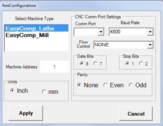
Select ACSource_EasyComp from the Select Compensation Source Machine dialog box.
Set RS232 port connected to EasyComp and parameters according to EasyComp documentation and press Apply.
ACSource_EasyComp is now configured.
"FanucDNC Control"
Select ACSource_FanucDNC from the Select Compensation Source Machine dialog box.
Enter all the required data and press Apply.
ACSource_FanucDNC is now configured.
"FileSystem CNC Interface"
The FileSystem CNC interface produces formatted data files, by routine or dimension, for access by operators or by other applications. It does not communicate directly with any CNC.
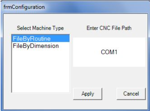
Select ACSource_FileSystem from the Select Compensation Source Machine dialog box.
- Choose how the files are to be created, by selecting one of the options in the Select Machine Type list:
- If File by Routine is chosen, AutoComp creates a file with data for each dimension in the routine (one dimension per line, in the order of the routine). The data file is named <routine name>.csv..
- If File by Dimension is chosen, AutoComp creates a separate file for each dimension. Each data file is named <routine name>_<dimension name>.csv.
- Specify the destination where CNC files are to be sent by clicking in the field under Enter CNC File Path. Browse to the desired location and select it.
- Press Apply to return to the System Configuration window.
ACSource_FileSystem is now configured.
"Focas1 and Focas2 Control"
ACSource_Focas1 supports both Focas1 and Focas2 controls, via Ethernet or HSSB.
Select the Focas CNC from the Select Compensation Source Machine dialog box.
- Specify the IP address of the CNC as follows: o
- Select IPV4 IP, DNS, or HSSB
- Enter the IP address, DNS Name or HSSB Node and then press OK.
- The IP address, DNS Name or HSSB Node is displayed in the field below the radio buttons.
- The default Control IP Port is 8193. Verify this on the control.
- If the control has both mill and lathe axes, check the Complex Tool Offset checkbox.
- When AutoComp will communicate with a Moriseki NT series with a Fanuc control, click the Moriseki NT series checkbox on the configuration page.
- Select the Focas1 or 2 library as follows:
- Click on Select Focas1/2 libraries.
- A Browse for Folders dialog box is displayed that allows the user to select the desired library.
- Click on the desired library to select it. Select F1lib for a Focas1 control, and F2Lib for a Focas2 control.
- Click on Select Focas1/2 libraries.
- Press Apply.
ACSource_Focas1 is now configured.
Note: If there are communication issues, check the Fanuc parameter for DHCP on the control. Generally, the parameter is 14880 bit 6, but check the control documentation. This bit should be CLEAR to allow setting a static IP address.
"FTP Control"
If a system uses an FTP control, contact CEI. CEI can customize FTP data for the FTP site.
Select ACSource_FTP from the Select Compensation Source Machine dialog box.
A window is displayed much like the following. The fields where configuration information can be specified will vary depending on the system’s needs.
Enter all the required data and press Apply.
ACSource_FTP is now configured.
"GetPutReadWrite Control"
The ACSource_GetPutReadWrite control can be chosen with Okuma RS232 (Lathe or Mill). This requires a CEI CNC program to initiate the compensation and a special RS232 cable.
The configuration process is the same as for the Okuma RS232 CNC, except Lathe or Mill must be specified.
Note: The Send To Okuma DWELL field allows the user to enter a value for the time (seconds) between commands. 0.5 is the default. This time allows the Okuma to process the request before another is sent.
When finished configuring the GetPutReadWrite CNC interface, the gage converter(s) can be configured.
"Haas Control"
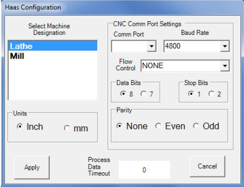
Select the ACSource_Haas control from the Select Compensation Source Machine dialog box.
CEI provides the ACSource_Haas control on request.
Note: If using this control, the CNC control setting 143 (parameter data) must be ON to enable AutoComp communication.
The following is from the Haas documentation. Haas COM port settings:
- Press the “SETNG/GRAPH” button to enter the setting pages. Use the page up/down buttons to scroll through the setting pages. Use the vertical cursor keys to move to the desired setting, or enter a setting number and press the down arrow button to go directly to that setting.
- Baud Rate Select: This setting allows the operator to change the rate at which data are transferred to/from the first serial port (RS-232). This applies to the upload/download of pro- grams etc. and to DNC functions. This setting must match the transfer rate from the personal computer.
- Parity Select: This setting defines parity for the first serial port (RS-232). When set to None, no parity bit is added to the serial data. When set to Zero, a 0 bit is added. Even and Odd work like normal parity functions. Know what the system needs, for example, XMODEM must use 8 data bits and no parity (set to “None”). This setting must match the transfer rate from the personal computer.
- Stop Bit: This setting designates the number of stop bits for the first serial port (RS-232). It can be 1 or 2. This setting must match the transfer rate from the personal computer.
- Synchronization: This changes the synchronization protocol between sender and receiver for the first serial port (RS-232). This setting must match the transfer rate from the personal computer. When set to RTS/CTS, the signal wires in the serial data cable are used to tell the sender to temporarily stop sending data while the receiver catches up.
- When set to XON/XOFF, the most common setting, ASCII character codes are used by the receiver to tell the sender to temporarily stop.
- The selection DC CODES is like XON/XOFF, except that paper tape punch or reader start/stop codes are sent. XMODEM is a receiver-driven communications protocol that sends data in blocks of 128 bytes. XMODEM has added reliability as each block is checked for integrity. XMODEM must use 8 data bits and no parity.
- 11 BAUD RATE SELECT: 38400 12 PARITY SELECT: NONE 13 STOP BIT: 1
- 14 SYNCHRONIZATION: XON/XOFF 37 RS-232 DATA BITS: 8
- 143 MACHINE DATA COLLECT: ON
- When finished configuring the Haas control, the gage converter(s) can be configured.
"Heidenhain Control"
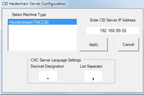
Select ACSource_Heidenhain from the Select Compensation Source Machine dialog box.
Note 1: The Heidenhain control requires network access to a running CEI Heidenhain server.
Enter the IP address of the system where the CEI CNC server is running, and press Apply.
Contact Caron Engineering for more information on the CEI CNC server.
Note 2: With the Heidenhain control, if an offset cannot be written, then a retry message will be displayed.
"MAPPSEIP Control"
Select ACSource_MAPPSEIP from the Select Compensation Source Machine dialog box.
AutoComp requires Ovation MAPPSCommUC2.dll to allow communication of data to Mori Seiki machines with the MAPPS III software.
Configure the EIP IP Address, Machine Number, Base Address, and MAPPSCOMM location fields according to Ovation documentation.
"Mazak Control"
If the system uses a Mazak control, first install and configure the CEI_MazakServer on the CNC itself. See "CEI_Mazak Installation and Configuration," packaged with the installation kit, for detailed information.
After installing and configuring the Mazak server, the Mazak CNC interface can be configured in AutoComp.
Note 1: If an offset cannot be written, then a retry message will be displayed. AutoComp will continue to retry until success, or until the next gage cycle is sent. If the latter, the dimension will be in an error state.
Note 2: The CEI_MazakServer supports Y740 and Y737 series controls.
Select and Configure Mazak CNC Interface
After installing and configuring the Mazak server on the CNC, the Mazak CNC interface can be selected in AutoComp.
- In AutoComp's Select Compensation Source Machine dialog box, select ACSource_Mazak as the CNC interface.
- In the Enter CNC IP Address field, enter the IP address of the Mazak control or the specific IP set when the CEI_Mazak server was configured.
- In the Number of MachineHeads field, enter the number of machine heads.
- In the Tool Page field, select ToolData Pages.
- The option to utilize the language decimal and list separator overrides is available.
- Press Apply.
ACSource_Mazak is now configured.
Note on Mazak Tool Names
The Mazak interface differs slightly from most other CNC interfaces, as detailed in the "CEI_Mazak Installation and Configuration" document included with the installation kit. The most notable difference is that Mazak uses tool names instead of offsets.
When using a Mazak control, clicking in the Routine Editor's Tool Name field displays the Select Tool By Head window. This win- dow displays all registered tool names.
When selecting the tool from the list, it is displayed in the Routine Editor's Tool Name field. See screen capture above. All other dimension features should be set as documented in the AutoComp manual/online help.
"Mitsubishi70/700V Control"
Select ACSource_Mitsubishi70/700V from the Select Compensation Source Machine dialog box.
AutoComp requires Mitsubishi Custom API VG.5 installed to use Mitsubishi70/700V control.
For Mistubishi, controls connection is on the control by default.
For Citizen and Mori Seiki, contact the machine dealer for the COMM data server package.
The Mitsubishi custom API library for ver.G5 must be installed on the AutoComp PC.
See the CNC parameter settings needed in the "Mitsubishi DataServer M70700" folder of the AutoComp installation package.
"OkumaLathe Control P200"
The ACSource_OkumaLathe interface is for use with the Okuma THINC API on an Okuma Lathe P200 control.
Note: AutoComp requires at least OkumaServer 2.5.
Select ACSource_OkumaLathe from the Select Compensation Source Machine dialog box.
Since there is only one machine type available in the Select Machine Type list, it does not need to be selected.
The CEI_OkumaAPI server must be running on the Okuma control for P200 controls.
1. Specify the DNS name or IP address of the CNC as follows:
- Select IPV4 IP or DNS.
- Click in the field
- Enter the computer name or IP address and then press OK.
Note: If AutoComp is running on the local control and the CEI server is using the default local IP address, 0 (zero) may be entered for the CNC IP address.
The computer name or IP address is displayed in the Enter CNC IP Address field.
2. Press Apply.
ACSource_OkumaLathe is now configured.
"OkumaLathe Control P300"
The ACSource_OkumaLatheP300 interface is for use with the Okuma THINC API on an Okuma Lathe P300 control.
Select ACSource_OkumaLatheP300 from the Select Compensation Source Machine dialog box.
Since there is only one machine type available in the Select Machine Type list, it does not need to be selected.
The CEI_OkumaAPI server must be running on the Okuma control for P300 controls.
1. Specify the DNS name or IP address of the CNC as follows:
- Select IPV4 IP or DNS.
- Click in the field.
- Enter the computer name or IP address using the keypad and then press OK.
Note: If AutoComp is running on the local control and the CEI server is using the default local IP address, 0 (zero) may be entered for the CNC IP address.
2. Press Apply.
ACSource_OkumaLatheP300 is now configured.
"OkumaMachining Control"
If a system is an Okuma Mill P200 or P300 control with Okuma THINC API, the ACSource_OkumaMachining interface can be used.
Note: AutoComp requires at least OkumaServer 2.5 on a P200 Control.
Select ACSource_OkumaMachining from the Select Compensation Source Machinedialog box.
Since there is only one machine type available in the Select Machine Type list, it does not need to be selected.
Note: P300 is also supported by the Machining selection.
The CEI_OkumaAPI server must be running on the Okuma control for P200 controls. The CEI_OkumaP300 server must be running on the Okuma control for P300 controls.
1. Specify the DNS name or IP address of the CNC as follows:
- Select IPV4 IP or DNS
- Enter the computer name or IP address using the keypad and then press OK.
Note: If AutoComp is running on the local control and the CEI server is using the default local IP address, 0 (zero) may be entered for the CNC IP address.
2. Press Apply.
ACSource_OkumaMachining is now configured.
"OkumaRS232PP Control"
This CNC interface is for any Okuma non-P200 machine that has the post processing option enabled. For information on enabling this option, see the Control setup and RS232 cable and configuration instructions in the Control Programs and Con- figuration\OkumaRS232PP folder of the AutoComp installation package.
Select ACSource_OkumaRS232PP from the Select Compensation Source Machine dialog box.
Enter all the required data for the machine.
CommPort is the Comm Port on the local AutoComp PC that is connected to the machine serial port. Other CommPort settings should match those of the machine serial port.
When finished entering the required data, press Apply.
ACSource_OkumaRS232PP is now configured.
Note: ACSource_GetPutReadWrite CNC interface can also be used for Okuma RS232 machines.
"Siemens Windows Control(840D w/DDE support)"
If using a Siemens 840D Windows control prior to the SolutionLine series, first install and configure the CEI_SiemensServer on the CNC itself.
Note: AutoComp requires CEI_SiemensDDEConnect to be installed. See "CEI_Siemens Installation and Configuration," packaged with the installation kit, for detailed information.
After installing and configuring the Siemens server, the Siemens Windows CNC interface can be selected in AutoComp.
Select and Configure Siemens Windows CNC Interface
After installing and configuring the Siemens server on the CNC, the Siemens Windows CNC interface can be selected in AutoComp.
- In the Select Compensation Source Machine window, select ACSource_Siemens as the CNC interface.
- In the Enter CNC IP Address field, enter the IP address of the Siemens control, or the specific IP set when the CEI_ Siemens server was configured.
- The EnableOffsets box is checked by default. Uncheck the box it if using the legacy ‘variable only’ CEI Seimens OPC server.
- The CNC Language Settings fields:
- Decimal Designation is set by default to a period (used in the USA, e.g. 99.01). In many countries, a comma is used (e.g. 99,01). To change this field, simply type a period or comma in the Decimal Designation field.
- List Separator used in ascii files, is set by default to a comma (used in the USA). In many other countries, includ- ing Germany and France, the list separator is a semicolon (;). To change this field, simply type a comma or semi- colon in the List Separator field
- Press Apply.
ACSource_Siemens is now configured.
Note on Siemens Tool Names
The Siemens Windows interface differs slightly from most other CNC interfaces, as detailed in the "CEI_Siemens Installation and Configuration" document included with the installation kit. The most notable difference is that Siemens uses tool names instead of offsets.
When using Siemens Windows control, clicking in the AutoComp Routine Editor's Tool Name field displays the Select Tool By Head window. This window displays all registered tool names.
Note: The "Head" designation is a generic term used for CNCs that have multiple tool lists (for example, Mazak). The Siemens CNC has only one list.
Double click to select the tool from the list and place it in the Routine Editor's Tool Name field. The Offset and Path will be filled in on selection.
Note: If the tool list is very long, the first part of a tool name can be entered in the tool list's Find field to filter through the tool names.
All other AutoComp dimension features should be set as documented.
"SiemensOperate"
If using a Siemens Operate Windows control, first install and configure the CEI_SiemensServer on the CNC itself.
After installing and configuring the Siemens server, the Siemens Windows CNC interface can be selected in AutoComp.
Select and Configure Siemens Operate CNC Interface
After installing and configuring the Siemens server on the CNC, the Siemens Operate Windows CNC interface can be selected in AutoComp.
- In AutoComp's Select Compensation Source Machine win- dow, select ACSource_SiemensOperate as the CNC inter- face.
- If using a Siemens Operate Windows control, first install and con- figure the CEI_SiemensServer on the CNC itself.
- After installing and configuring the Siemens server, the Siemens Windows CNC interface can be selected in AutoComp.
- In the Enter CNC IP Address field, enter the IP address of the Siemens control, or the specific IP set when the CEI_ Siemens server was configured.
- The CNC Language Settings fields:
- Decimal Designation is set by default to a period (used in the USA, e.g. 99.01). In many countries, a comma is used (e.g. 99,01). To change this field, simply type a period or comma in the Decimal Designation field.
- List Separator used in ascii files, is set by default to a comma (used in the USA). In many other countries, including Germany and France, the list separator is a semicolon ( ; ). To change this field, simply type a comma or semi- colon in the List Separator field
- Press Apply.
ACSource_SiemensOperate is now configured. For more information on how using Siemens Operate affects the routine editor see "CEI SERVER on Siemens Operate Windows Deployment" packaged with the installation kit.
"TestCNC Control"
The Test CNC option allows the user to explore the AutoComp system in demo mode.
Select ACSource_TestCNC from the Select Compensation Source Machinedialog box. See Select the CNC Interface for the System. No further configuration is necessary.
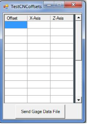
When the Test CNC interface is selected, the Test CNC Offsets window is always displayed.
This window allows loading test data files manually. It also displays the test file offset data table.
Note: When activating AutoComp licensing, enter the AutoComp Demonstration license to access and use only the TestCNC. The demonstration license is "-98765". The Test CNC interface is usable with a regular AutoComp license as well.

