No edit summary |
|||
| Line 1: | Line 1: | ||
[[Category:TMAC]] | [[Category:TMAC]] | ||
[[:Category:TMAC|Back to TMAC Categories]] | |||
== '''Overview''' == | == '''Overview''' == | ||
Revision as of 15:06, 31 August 2022
Overview
Based on how TMAC is interfaced with the control, commands can be issued to TMAC in the following methods:
- RS232 Commands: Commands are passed through RS232 protocol using ASCII command strings
- File drop: Commands are passed using ASCII command strings in a text file that is dropped into a file directory monitored by TMAC
- Variable: Commands are passed through variables in the part program
- Parallel I/O: Commands are passes to TMAC using configured I/O bits
The following sections provide a list of commands for various TMAC interfaces. Example command string formats and rules are also provided for each command type.
Note: CEI may be able to supply CNC specific macros to build the command strings discussed in this chapter.
RS232 Commands
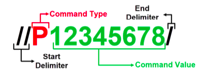
In an RS232 command interface, a command is a string of characters that is built by the CNC and is sent to and parsed by TMAC. These character strings can indicate a monitoring or non-monitoring/function command. The character string format for non-monitoring/function commands can be seen below.
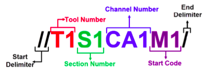
For monitoring commands, the letters and subsequent numbers in the command string each represent a necessary piece of information that TMAC needs to monitor an operation. At a minimum, this entails the following characters:
- T######## - designates the tool number for the operation; Maximum of eight digits
- S## - designates the section number for the operation; Maximum of 2 digits
- CA######## - designates the single-digit channel numbers(Channel 1, channel 2, Channel 3, etc...) for the operation. A maximum of 8 channels can be designated in this manner.
- CB######## - designates the double-digit channel numbers (Channel 11, channel 12, Channel 13, etc...) for the operation. A maximum of 4 channels can be designated in this manner. TMAC also parses double digit channels in the command string as CC, CD, CE...etc.
- M1 - designates a start monitor, must be at the end of the command string
Issuing RS232 Commands for Multichannel Starts
TMAC allows a single command to start monitoring for multiple channels at the same time. Multichannel RS232 commands can be issued using two methods:
- using a channel group or
- by including each channel in the command string
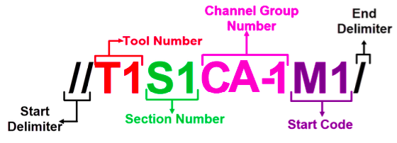
If a channel group(s) has been created, a multichannel start command can be issued using the channel group ID as seen below. When using a channel group, the start command is issued for all channels set in the group.
Example 1
This command starts TMAC and monitors Tool 1, Section 1 for channels 1,5 12 and 13.
Example 2
This command starts TMAC and monitors Tool 1, Section 1 for channels 1-12. Due to the character limit for CA, channel 9 must be passed with CB.
RS232 Monitoring Commands
Non-Monitoring/function RS232 Commands
Variable Commands
In a variable interface, TMAC utilizes a command variable set in the con- figuration to receive commands from a CNC part program. Depending on the command type, TMAC may utilize several variables to issue commands. For single channel monitoring commands, TMAC only utilizes the command variable set in the configuration. If no channel is specified in the command variable, TMAC
For non-monitoring commands TMAC utilizes the command variable and a parameter variable. The parameter variable is the next consecutive variable from the designated command variable. For example if the command variable is set as 90, the parameter variable is 91.
Note: The parameter variable must be populated before the command variable because the values passed to the command variable utilize the data stored in the parameter variable.
Issuing Variable Commands for Multichannel Starts
TMAC allows a single command to start monitoring for multiple channels at the same time. Multichannel variable commands are similar to single channel variable commands with a few differences. Multichannel variable commands utilize one command variable and at least one consecutive variable. The additional variable(s) designate which channels to start in the command and are referred to as channel designation variables in the documentation. The channel designation variables must be set using the following rules:
- Single digit channel numbers are stored in the first variable;
- Double digit and single digit channel numbers are stored in the second variable
- Channel groups are designated by a negative value
TMAC utilizes the command passed through the command variable to determine whether the command is a multichannel start or not. If not channel number is specified in the command variable, TMAC polls the additional variables for the multichannel start. The following examples display various ways multichannel commands can be implemented in a Variable interface:
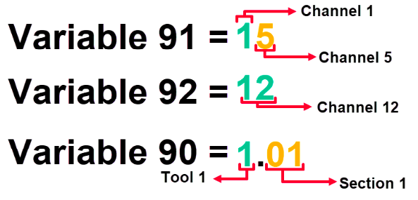
Example 1
Consider the following example multichannel command:
- The command variable is 90 and the channel designation variables are 91 and 92
- The designated operation requires a multichannel start for channel numbers 1, 5 and 12
- The operation is using Tool 1 and Section 1
Example 2
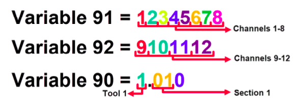
The following example displays a multichannel start that requires more than 8 single digit channels:
- The command variable is 90 and the channel designation variables are 91 and 92
- The designated operation requires a multichannel start for channel numbers 1-12
- The operation is using Tool 1 and Section 1
- The 9th single digit channel is stored first in the second channel designation variable
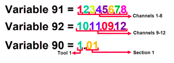
Example 3
The following example displays a multichannel start that requires more than 8 single digit channels:
- The command variable is 90 and the channel designation variables are 91 and 92
- The designated operation requires a multichannel start for channel numbers 1-12
- The operation is using Tool 1 and Section 1
- The 9th single digit channel is not stored first in the second channel designation variable
Example 4
Consider the following example multichannel command:
- The command variable is 90 and the channel designation variable is 91
- The designated operation requires a multichannel start for channel group 1
- The operation is using Tool 1 and Section 1
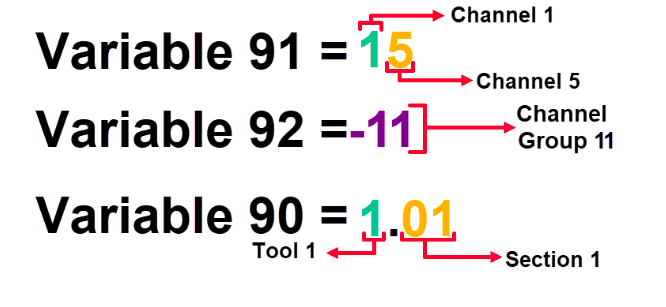
Example 5
Consider the following example multichannel command:
- The command variable is 90 and the channel designation variables are 91 and 92
- The designated operation requires a multichannel start for channel numbers 1, 5 and channel group 11
- The operation is using Tool 1 and Section 1
Variable Monitoring Commands
Variable Non-Monitoring Commands
Preload Commands
In some machining processes, timing issues in the part program can prevent TMAC from executing commands at the correct time. This can cause tools to not be monitored or to be monitored incorrectly. To prevent this, TMAC is capable of "preloading" a command. Preload is set by doing the following:
- Variable Command: Passing a negative value in the command variable
- RS232 Command: Passing a command string in the same format in previous example
Note: CEI may be able to provide CNC specific sub-programs to build the preload RS232 command string.
When TMAC receives a preload command, it prepares but does not immediately execute the command. TMAC then waits for a configured CNC output to set the preload input on the TCU high. When the preload input is set high, TMAC immediately executes the preloaded command. This allows more flexibility when adding TMAC commands in the CNC part program, eliminating any timing issues.
Millivolt Command String Example
The command designator for Millivolt commands is 30.
TMAC constantly polls the CNC Command Variable for this value if mV commands are enabled in the configuration. When 30 is stored in the programmed CNC Command Variable, TMAC polls the next 11 variables for values to use for various monitoring parameters. Each parameter variable is associated with a certain monitoring parameter.
For this example, let the CNC Command Variable be 90. The parameter variables are 91-101 and are associated with monitoring parameters as seen in table below
The Millivolt command string is as follows:
Example: Issuing a Millivolt Command
When a Millivolt command is issued through a part program, TMAC polls the parameter variables and replaces the asterisks seen
If a parameter variable has a stored value of "0", the associated parameter is removed from the command string. In this case the Undercut Limit parameter variable has a value of "0", so the command received by the TMAC process is as follows:
Parallel I/O Commands
When TMAC is configured with a Parallel I/O command interface, commands are issued to TMAC by setting I/O bits high to determine Tool, Section and Channel number. When TMAC is configured, the system integrator assigns a number of bits to input banks for channel, Tool and section number. These bits have a value of "1" when set high and a value of "0" when set low. The com- bination of bit values make a binary number that instructs TMAC which Tool, Section and Channel to insert into the command. Additionally a bit is assigned to a data strobe that sends the command
Consider the following TMAC configuration:
- Tool bits assigned: 4
- Section bits assigned: 4
- Channel bits assigned: 3
To issue a start command for Channel 1, Tool 5, Section 4 set the bits as follows:
Once the Tool, Section and Channel number are set using the input banks, the command is sent by setting the strobe bit from low to high. In order to issue a stop command to TMAC, all Tool, Section, and Channel bits low need to be set low. The stop command can then be issued by setting the data stobe bit from low to high.
