No edit summary |
No edit summary |
||
| (4 intermediate revisions by the same user not shown) | |||
| Line 1: | Line 1: | ||
[[Category:TMAC]] | [[Category:TMAC]] | ||
[[ | [[TMAC|Back to TMAC Home Page]] | ||
== '''Overview''' == | == '''Overview''' == | ||
| Line 27: | Line 27: | ||
## Entering a value of 0 disables the Extreme Limit | ## Entering a value of 0 disables the Extreme Limit | ||
# Click SAVE | # Click SAVE | ||
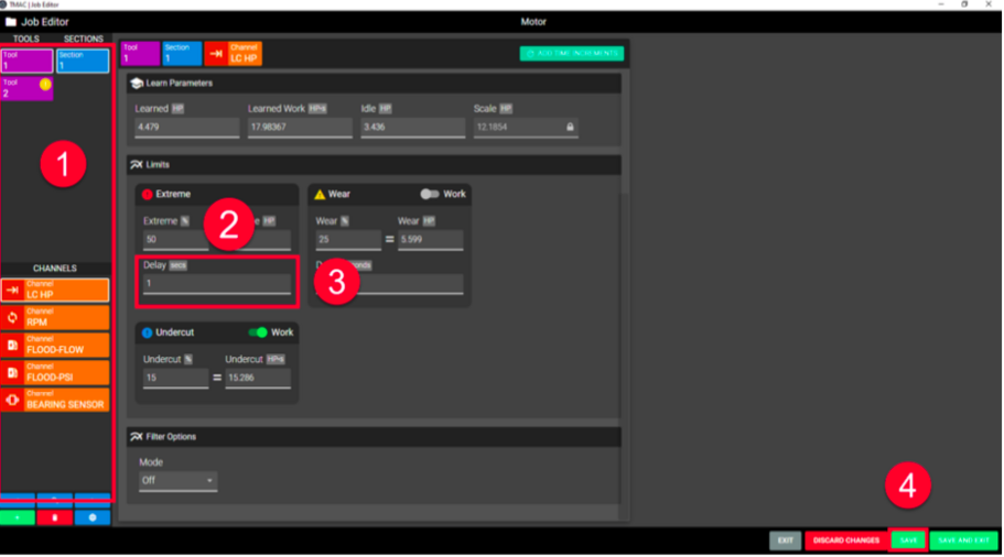
[[File:Screen Shot 2022-09-14 at 8.31.00 AM.png|center|thumb|767x767px|Setting Extreme Limit ]] | |||
'''Note:''' Although the above step list specifies entering a percentage for the limit, a direct value may be entered in the other field outlined in step 3 in the figure above. When a limit is set in either field, the other field is automatically populated. | '''Note:''' Although the above step list specifies entering a percentage for the limit, a direct value may be entered in the other field outlined in step 3 in the figure above. When a limit is set in either field, the other field is automatically populated. | ||
| Line 42: | Line 42: | ||
## Entering a value of 0 disables the Extreme alarm delay | ## Entering a value of 0 disables the Extreme alarm delay | ||
# Click SAVE | # Click SAVE | ||
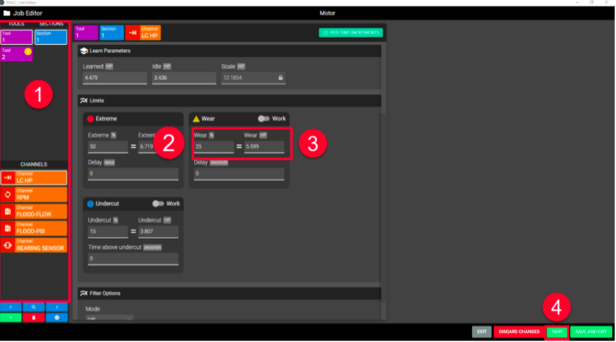
[[File:Setting Extreme Delay.png|center|thumb|911x911px|Setting Extreme Delay ]] | |||
== '''Wear Limit''' == | == '''Wear Limit''' == | ||
| Line 57: | Line 58: | ||
## Entering a value of 0 disables the Wear Limit | ## Entering a value of 0 disables the Wear Limit | ||
# Click SAVE | # Click SAVE | ||
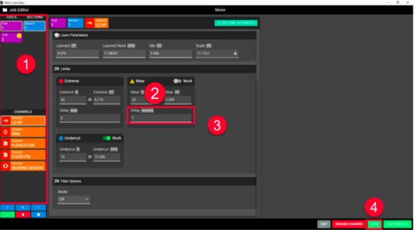
[[File:Setting Wear Limit.png|center|thumb|880x880px|Setting Wear Limit]] | |||
'''Note:''' Although the above step list specifies entering a percentage for the limit, a direct value may be entered in the other field outlined in step 3 in the figure above. When a limit is set in either field, the other field is automatically populated. | '''Note:''' Although the above step list specifies entering a percentage for the limit, a direct value may be entered in the other field outlined in step 3 in the figure above. When a limit is set in either field, the other field is automatically populated. | ||
| Line 72: | Line 73: | ||
## Entering a value of 0 disables the Wear Alarm Delay | ## Entering a value of 0 disables the Wear Alarm Delay | ||
# Click SAVE | # Click SAVE | ||
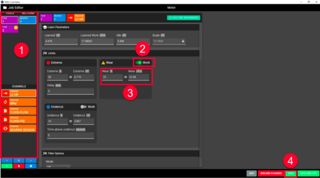
[[File:Setting Wear Alarm Delay.png|center|thumb|595x595px|Setting Wear Alarm Delay]] | |||
==== '''''Setting a Work Wear Limit''''' ==== | ==== '''''Setting a Work Wear Limit''''' ==== | ||
| Line 82: | Line 84: | ||
## Entering a value of 0 disables the Wear Limit | ## Entering a value of 0 disables the Wear Limit | ||
# Click SAVE | # Click SAVE | ||
[[File:Setting Work Wear Limit.png|center|thumb|655x655px|Setting Work Wear Limit ]] | |||
== '''Undercut Limit''' == | == '''Undercut Limit''' == | ||
| Line 99: | Line 102: | ||
## Entering a value of 0 disables the Undercut Limit | ## Entering a value of 0 disables the Undercut Limit | ||
# Click SAVE | # Click SAVE | ||
[[File:Setting the Undercut Limit.png|center|thumb|695x695px|Setting the Undercut Limit ]] | |||
'''Note:''' Although the above step list specifies entering a percentage for the limit, a direct value may be entered in the other field outlined in step 3 in the figure above. When a limit is set in either field, the other field is automatically populated. | '''Note:''' Although the above step list specifies entering a percentage for the limit, a direct value may be entered in the other field outlined in step 3 in the figure above. When a limit is set in either field, the other field is automatically populated. | ||
| Line 116: | Line 119: | ||
## Entering a value of 0 disables the Time Above Undercut Feature | ## Entering a value of 0 disables the Time Above Undercut Feature | ||
# Click SAVE | # Click SAVE | ||
[[File:Setting Time Above Undercut.png|center|thumb|844x844px|Setting Time Above Undercut ]] | |||
==== '''''Setting a Work Undercut Limit''''' ==== | ==== '''''Setting a Work Undercut Limit''''' ==== | ||
| Line 126: | Line 130: | ||
### Entering a value of 0 disables the Undercut Limit | ### Entering a value of 0 disables the Undercut Limit | ||
# Click Save | # Click Save | ||
[[File:Screen Shot 2022-09-14 at 8.58.38 AM.png|center|thumb|850x850px|Setting Time Above Undercut ]] | |||
== '''Spindle Speed Limits''' == | == '''Spindle Speed Limits''' == | ||
| Line 147: | Line 152: | ||
## Entering a value of 0 disables the Upper Spindle Limit | ## Entering a value of 0 disables the Upper Spindle Limit | ||
# Click Save | # Click Save | ||
[[File:Setting Upper Spindle Limit.png|center|thumb|790x790px|Setting Upper Spindle Limit ]] | |||
==== '''''Setting an Upper Limit Delay''''' ==== | ==== '''''Setting an Upper Limit Delay''''' ==== | ||
| Line 155: | Line 161: | ||
# Enter the amount of time the spindle speed is allowed to exceed the upper limit | # Enter the amount of time the spindle speed is allowed to exceed the upper limit | ||
# Click SAVE | # Click SAVE | ||
[[File:Setting Upper Limit Delay.png|center|thumb|848x848px|Setting Upper Limit Delay ]] | |||
=== '''Setting a Lower Spindle Limit''' === | === '''Setting a Lower Spindle Limit''' === | ||
| Line 168: | Line 175: | ||
## Entering a value of 0 disables the Lower Spindle Limit | ## Entering a value of 0 disables the Lower Spindle Limit | ||
# Click SAVE | # Click SAVE | ||
[[File:Setting Lower Limit.png|center|thumb|822x822px|Setting Lower Limit ]] | |||
==== '''''Setting a Lower Limit Delay''''' ==== | ==== '''''Setting a Lower Limit Delay''''' ==== | ||
| Line 176: | Line 184: | ||
# Enter the amount of time the spindle speed is allowed to fall below the lower limit | # Enter the amount of time the spindle speed is allowed to fall below the lower limit | ||
# Click SAVE | # Click SAVE | ||
[[File:Setting Lower Limit Delay.png|center|thumb|817x817px|Setting Lower Limit Delay ]] | |||
== '''Coolant Limits''' == | == '''Coolant Limits''' == | ||
| Line 193: | Line 202: | ||
# Enter the percentage above the learned coolant flow/pressure that will trigger a High alarm condition. | # Enter the percentage above the learned coolant flow/pressure that will trigger a High alarm condition. | ||
# Click Save | # Click Save | ||
[[File:Setting a High Coolant Limit.png|center|thumb|545x545px|Setting a High Coolant Limit ]] | |||
=== '''Setting a Low Warning Coolant Limit''' === | === '''Setting a Low Warning Coolant Limit''' === | ||
| Line 201: | Line 211: | ||
# Enter the percentage below the Learned Coolant Flow/Pressure that will trigger a Low Warning alarm condition. | # Enter the percentage below the Learned Coolant Flow/Pressure that will trigger a Low Warning alarm condition. | ||
# Click Save | # Click Save | ||
[[File:Low Warning Coolant Limit.png|center|thumb|931x931px|Low Warning Coolant Limit ]] | |||
=== '''Setting a Low Coolant Limit''' === | === '''Setting a Low Coolant Limit''' === | ||
| Line 209: | Line 220: | ||
# Enter the percentage below the Learned Coolant Flow/Pressure that will trigger a Low alarm condition. | # Enter the percentage below the Learned Coolant Flow/Pressure that will trigger a Low alarm condition. | ||
# Click SAVE. | # Click SAVE. | ||
[[File:Setting Low Coolant Limit.png|center|thumb|782x782px|Setting Low Coolant Limit ]] | |||
=== '''Coolant Alarm Delay''' === | === '''Coolant Alarm Delay''' === | ||
| Line 220: | Line 232: | ||
# Enter the time in seconds for the alarm delay | # Enter the time in seconds for the alarm delay | ||
## Allowable values range from 0.1 to 320 seconds in 0.1 second increments | ## Allowable values range from 0.1 to 320 seconds in 0.1 second increments | ||
## Enter 0.0 to disable the coolant alarm delay Click Save | ## Enter 0.0 to disable the coolant alarm delay | ||
# Click Save | |||
# Repeat steps 2-4 for each limit that requires a delay | # Repeat steps 2-4 for each limit that requires a delay | ||
[[File:Setting Coolant Alarm Delays.png|center|thumb|720x720px|Setting Coolant Alarm Delays ]] | |||
== '''Extreme Feedrate Limit''' == | == '''Extreme Feedrate Limit''' == | ||
| Line 236: | Line 250: | ||
## Must be less than Wear Feedrate % Limit | ## Must be less than Wear Feedrate % Limit | ||
# Click Save | # Click Save | ||
[[File:Setting Extreme Feedrate Limit.png|center|thumb|753x753px|Setting Extreme Feedrate Limit ]] | |||
==== '''''Extreme Feedrate Alarm Delay''''' ==== | ==== '''''Extreme Feedrate Alarm Delay''''' ==== | ||
| Line 249: | Line 264: | ||
## Entering a value of 0 disables the Feedrate Extreme alarm delay | ## Entering a value of 0 disables the Feedrate Extreme alarm delay | ||
# Click SAVE | # Click SAVE | ||
[[File:Setting an Extreme Feedrate Alarm Delay.png|center|thumb|662x662px|Setting an Extreme Feedrate Alarm Delay ]] | |||
== '''Wear Feedrate Limit''' == | == '''Wear Feedrate Limit''' == | ||
| Line 263: | Line 279: | ||
## Must be greater than Extreme feedrate limit | ## Must be greater than Extreme feedrate limit | ||
# Click SAVE | # Click SAVE | ||
[[File:Setting the Wear Feedrate Limit.png|center|thumb|749x749px|Setting the Wear Feedrate Limit ]] | |||
'''Note:''' Use trial and error to determine the best setting. Remember, the lower the programmed wear feedrate, the longer the tool will cut before generating a wear feedrate alarm. | '''Note:''' Use trial and error to determine the best setting. Remember, the lower the programmed wear feedrate, the longer the tool will cut before generating a wear feedrate alarm. | ||
| Line 276: | Line 292: | ||
## Allowable values range from 0.1 to 320 seconds in 0.1 second increments | ## Allowable values range from 0.1 to 320 seconds in 0.1 second increments | ||
## Entering a value of 0 disables the feedrate Wear alarm delay | ## Entering a value of 0 disables the feedrate Wear alarm delay | ||
# Click | # Click SAVE | ||
[[File:Setting a Wear Feedrate Delay.png|center|thumb|593x593px|Setting a Wear Feedrate Delay ]] | |||
== '''Slope Limit''' == | == '''Slope Limit''' == | ||
| Line 285: | Line 302: | ||
* Slope parameters define the learned slope value for the operation | * Slope parameters define the learned slope value for the operation | ||
* Slope limits are calculated as a percentage above or below the learned slope | * Slope limits are calculated as a percentage above or below the learned slope | ||
[[File:Slope Limits versus Standard Limits.png|center|thumb|756x756px|Slope Limits versus Standard Limits ]] | |||
=== '''Setting Slope Limits''' === | === '''Setting Slope Limits''' === | ||
| Line 305: | Line 323: | ||
## If the Time Above Undercut is set, the signal value must exceed the undercut limit for the amount of time set. | ## If the Time Above Undercut is set, the signal value must exceed the undercut limit for the amount of time set. | ||
## If the Immediate switch is toggled, the functionality of the Undercut limit changes; An alarm is triggered when the signal value falls below the undercut limit. | ## If the Immediate switch is toggled, the functionality of the Undercut limit changes; An alarm is triggered when the signal value falls below the undercut limit. | ||
[[File:Setting Slope Limits Steps 1-4.png|center|thumb|530x530px|Setting Slope Limits Steps 1-4 ]] | |||
[[File:Setting Slope Limits Steps 5a-c.png|center|thumb|534x534px|Setting Slope Limits Steps 5a-c ]] | |||
[[File:Setting Slope Limits Steps 7a-c.png|center|thumb|543x543px|Setting Slope Limits Steps 7a-c]] | |||
==== '''''Slope Sensitivity Examples''''' ==== | ==== '''''Slope Sensitivity Examples''''' ==== | ||
| Line 317: | Line 338: | ||
* Lower Warning: When the sensor signal falls below the learned profile by the value set for the limit, a warning alarm is triggered. | * Lower Warning: When the sensor signal falls below the learned profile by the value set for the limit, a warning alarm is triggered. | ||
* Lower Extreme: When the sensor signal falls below the learned profile by the value set for the limit, a critical alarm is triggered. | * Lower Extreme: When the sensor signal falls below the learned profile by the value set for the limit, a critical alarm is triggered. | ||
[[File:Signature Limit Example.png|center|thumb|Signature Limit Example ]] | |||
=== '''Setting Signature Limits''' === | === '''Setting Signature Limits''' === | ||
| Line 332: | Line 354: | ||
## If an alarm delay is set for the upper extreme or upper warning lim- its, an alarm is triggered when the signal value exceeds the limit for the amount of time set in the delay | ## If an alarm delay is set for the upper extreme or upper warning lim- its, an alarm is triggered when the signal value exceeds the limit for the amount of time set in the delay | ||
## If an alarm delay is set for the lower extreme or lower warning lim- its, an alarm is triggered when the signal value falls below the limit for the amount of time set in the delay | ## If an alarm delay is set for the lower extreme or lower warning lim- its, an alarm is triggered when the signal value falls below the limit for the amount of time set in the delay | ||
[[File:Setting Signature Limits Steps 1-2.png|center|thumb|528x528px|Setting Signature Limits Steps 1-2 ]] | |||
[[File:Setting Signature Limits Steps 3-4.png|center|thumb|529x529px|Setting Signature Limits Steps 3-4 ]] | |||
Latest revision as of 13:25, 26 October 2022
Overview
Every limit and delay programmed for an operation is stored in the job. Limits and delays can be edited at any time. The available limits for an operation depend on the channel class being monitored and if adaptive control is enabled.
Note: The limits and delays described in this chapter are not applicable to Millivolt operations.
Work (HP/s, kW/s) Limits
TMAC has the capability of using a work value for undercut and wear limits. Work limits (also known as "area under the curve") use signal value over time instead of peak values learned during an operation. Spikes in signal can satisfy undercut limits or trigger wear alarms unnecessarily. This can be prevented by using work limits.
For example: If a power spike reaches a value over the undercut limit but immediately comes back down under the limit, the undercut limit is satisfied, and the process continues. If the power stays below the undercut limit after the spike, the desired output is an alarm condition.
Work limits can only be applied to primary channel operations.
Extreme Limit
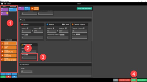
The Extreme Limit signals a catastrophic event (e.g., a severely worn or broken tool). When the signal value exceeds the extreme alarm for the amount of time specified in the Extreme Alarm Delay, TMAC halts monitoring and triggers an Extreme Alarm. The extreme limit is set at a percentage above the learned value for a given operation.
Setting the Extreme Limit
To set an Extreme Limit use the following steps:
- Specify the operation by selecting the tool, section, and channel from the lists on the left side of the Job Editor. The selected operation is displayed at the top of the Job Editor.
- In the Limits section of the Job Editor, click the Extreme Limit % field
- Enter the percentage above the learned value that will trigger an extreme alarm condition.
- Allowable values range from 1% to 999%
- Entering a value of 0 disables the Extreme Limit
- Click SAVE
Note: Although the above step list specifies entering a percentage for the limit, a direct value may be entered in the other field outlined in step 3 in the figure above. When a limit is set in either field, the other field is automatically populated.
Extreme Alarm Delay
The extreme alarm delay specifies a time period during which the signal value exceeds the extreme limit without triggering an alarm. This allows for brief spikes without unnecessary alarms.
Setting an Extreme Alarm Delay
In the Job Editor:
- Specify the operation by selecting the tool, section, and channel from the lists on the left side of the Job Editor. The selected operation is displayed at the top of the Job Editor.
- In the Extreme Limit section of the Job Editor, click the Delay field
- Enter the duration of the extreme delay
- Allowable values range from 0.1 to 320 seconds in 0.1 second increments
- Entering a value of 0 disables the Extreme alarm delay
- Click SAVE
Wear Limit
The Wear Limit alerts the operator that a tool has reached its optimum wear point and should be changed. An alarm activates immediately when signal value exceeds the Wear Limit, unless a Wear Alarm Delay is set. The Wear Limit is a percentage value above the learned value for an operation.
The user may need to experiment with different tools and parts to arrive at the best Wear Limit for a given set of conditions. Once appropriate limits are determined for all the machining processes, a direct and repeatable relationship to tool condition will be noticeable.
Setting the Wear Limit
To set a Wear Limit:
- Specify the operation by selecting the tool, section, and channel from the lists on the left side of the Job Editor. The selected operation is displayed at the top of the Job Editor.
- In the Limits section of the Job Editor, click the Wear Limit % field
- Enter the percentage above the learned value that will trigger a wear alarm condition.
- Allowable values range from 1% to 999%
- Entering a value of 0 disables the Wear Limit
- Click SAVE
Note: Although the above step list specifies entering a percentage for the limit, a direct value may be entered in the other field outlined in step 3 in the figure above. When a limit is set in either field, the other field is automatically populated.
Wear Alarm Delay
The Wear Alarm Delay specifies a time period during which the signal value for an operation may exceed the wear limit without triggering an alarm. This allows for brief signal spikes without unnecessary alarms.
Setting a Wear Alarm Delay
In the Job Editor:
- Specify the operation by selecting the tool, section, and channel from the lists on the left side of the Job Editor. The selected operation is displayed at the top of the Job Editor.
- In the Wear Limit section of the Job Editor, click the Delay field
- Enter the duration of the wear delay
- Allowable values range from 0.1 to 320 seconds in 0.1 second increments
- Entering a value of 0 disables the Wear Alarm Delay
- Click SAVE
Setting a Work Wear Limit
To set a work wear limit use the following steps:
- Specify the operation by selecting the tool, section, and channel from the lists on the left side of the Job Editor. The selected operation is displayed at the top of the Job Editor.
- In the Limits section of the Job Editor, click the Work toggle switch
- Enter the percentage above the Learned Work value that will trigger an alarm.
- Allowable values range from 1% to 999%
- Entering a value of 0 disables the Wear Limit
- Click SAVE
Undercut Limit
The Undercut Limit alerts the user to an incomplete machining process (e.g., a broken or missing tool).
The Undercut Limit is programmed as a percentage below the learned value for an operation. If the signal value fails to exceed the undercut limit for the amount of time specified in the Time Above Undercut field, TMAC generates an under-cut alarm when it receives a stop command.
Note: If using time increments, the undercut alarm is generated at the end of the time increment instead of the next stop monitor command.
Setting the Undercut Limit
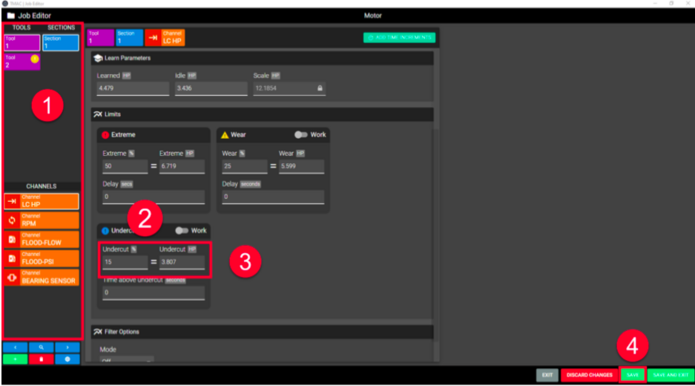
To set an Undercut Limit:
- Specify the operation by selecting the tool, section, and channel from the lists on the left side of the Job Editor. The selected operation is displayed at the top of the Job Editor.
- In the Limits section of the Job Editor, click the undercut Limit % field
- Enter the percentage below the learned value that will trigger an undercut alarm condition.
- Allowable values range from 1% to 99%
- Entering a value of 0 disables the Undercut Limit
- Click SAVE
Note: Although the above step list specifies entering a percentage for the limit, a direct value may be entered in the other field outlined in step 3 in the figure above. When a limit is set in either field, the other field is automatically populated.
Time Above Undercut
The Time Above Undercut feature is a timer that adds an additional requirement to trigger an undercut alarm. When using Time Above Undercut, an undercut alarm is triggered when the signal value fails to exceed the undercut limit for a specified duration. The Time Above Undercut limit is cumulative. TMAC accumulates the time while the signal value exceeds the undercut limit.
If the time is equal to or greater than the limit, no alarm is triggered. An alarm is generated only when the total time the signal value exceeds the undercut limit is less than the programmed time above undercut. The best way to arrive at an undercut time is to use the Data Viewer and measure the duration that the signal value exceeds the undercut limit.
Setting a Time Above Undercut
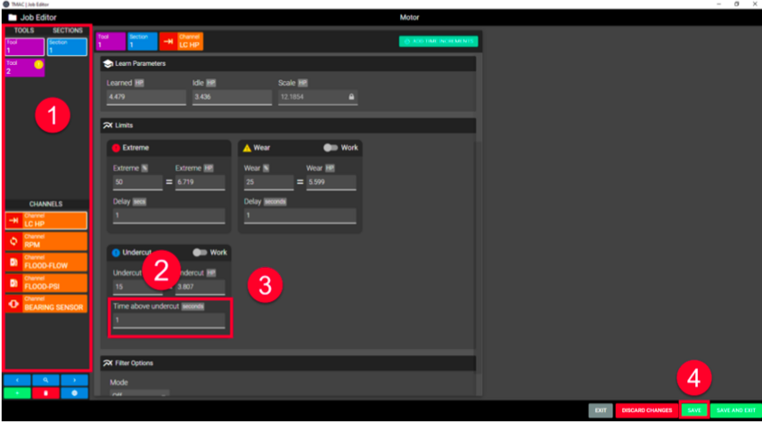
In the Job Editor
- Specify the operation by selecting the tool, section, and channel from the lists on the left side of the Job Editor. The selected operation is displayed at the top of the Job Editor.
- In the Undercut Limit section of the Job Editor, click the Time Above Undercut field
- Enter the desired Time Above Undercut time
- Allowable values range from 0.1 to 320 seconds in 0.1 second increments
- Entering a value of 0 disables the Time Above Undercut Feature
- Click SAVE
Setting a Work Undercut Limit
To set a work undercut limit use the following steps:
- Specify the operation by selecting the tool, section, and channel from the lists on the left side of the Job Editor. The selected operation is displayed at the top of the Job Editor.
- In the Limits section of the Job Editor, click the Work toggle switch
- Enter the percentage below the learned work value that will trigger an alarm.
- Allowable values range from 1% to 99%
- Entering a value of 0 disables the Undercut Limit
- Allowable values range from 1% to 99%
- Click Save
Spindle Speed Limits
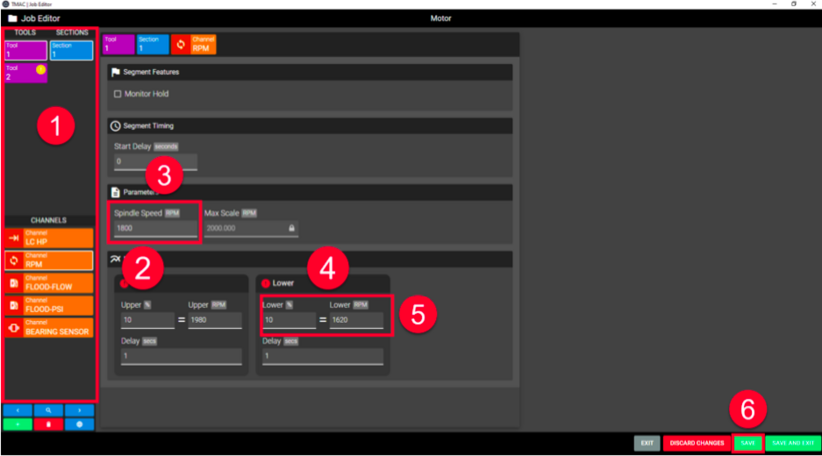
Spindle Speed monitoring tests the measured spindle speed of the machine against an upper and lower limit. TMAC checks the spindle speed between every Start and Stop monitor command. If the speed exceeds the upper limit or falls below the lower limit by the specified percentage:
- An alarm is triggered
- Tool monitoring is halted
Note: If a start delay is used, the spindle speed threshold does not take effect until the start delay has timed out.
Setting an Upper Spindle Limit
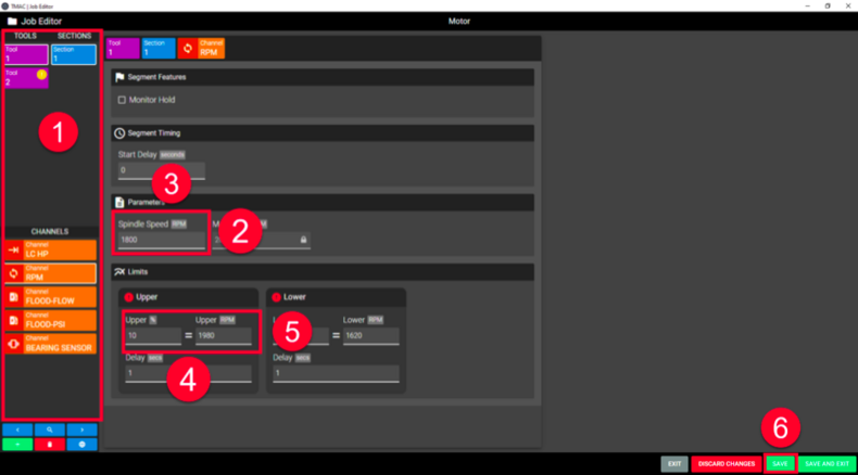
In the Job Editor:
- Specify the operation by selecting the tool, section, and channel from the lists on the left side of the Job Editor. The selected operation is displayed at the top of the Job Editor.
- In the parameters section of the Job editor, click the Spindle Speed field
- Enter a target spindle speed for the operation. Typically this matches the spindle speed set in the part program
- Valid values are 0-99999
- In the Limits section of the Job Editor, click the Upper Limit % field
- Enter the percentage above target spindle speed that will trigger an Upper alarm condition.
- Allowable values range from 0% to 99%
- Entering a value of 0 disables the Upper Spindle Limit
- Click Save
Setting an Upper Limit Delay
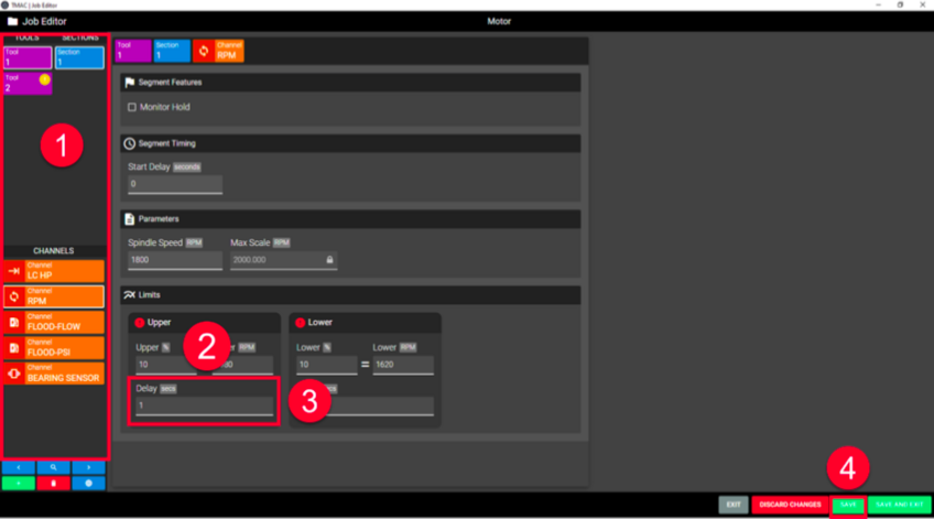
An Upper Limit Delay allows the spindle speed to surpass the upper limit for a specified amount of time before an alarm is triggered. To set an Upper Limit Delay use the following steps:
- Specify the operation by selecting the tool, section, and channel from the lists on the left side of the Job Editor. The selected operation is displayed at the top of the Job Editor.
- In the Limits section of the Job Editor, click Upper Delay field
- Enter the amount of time the spindle speed is allowed to exceed the upper limit
- Click SAVE
Setting a Lower Spindle Limit
In the Job Editor:
- Specify the operation by selecting the tool, section, and channel from the lists on the left side of the Job Editor. The selected operation is displayed at the top of the Job Editor.
- In the parameters section of the Job editor, click the Spindle Speed field
- Enter a target spindle speed for the operation. Typically this matches the spindle speed set in the part program
- Valid values are 0-99999
- In the Limits section of the Job Editor, click the Lower Limit % field
- Enter the percentage below the target spindle speed that will trigger a Lower alarm condition.
- Allowable values range from 0% to 99%
- Entering a value of 0 disables the Lower Spindle Limit
- Click SAVE
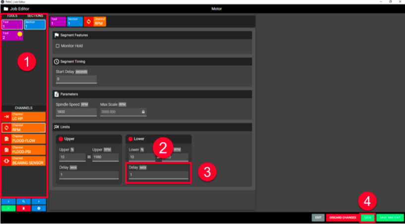
Setting a Lower Limit Delay
A Lower Limit Delay allows the spindle speed to fall below the lower limit for a specified amount of time before an alarm is triggered. To set a Lower Limit Delay use the following steps:
- Specify the operation by selecting the tool, section, and channel from the lists on the left side of the Job Editor. The selected operation is displayed at the top of the Job Editor.
- In the Limits section of the Job Editor, click the Lower Delay field
- Enter the amount of time the spindle speed is allowed to fall below the lower limit
- Click SAVE
Coolant Limits
Coolant monitoring measures either coolant flow or coolant pressure against programmed limits. Alarms are triggered when the coolant flow/pressure deviates outside of the programmed limits. The available limits are as follows:
- High: When coolant flow or pressure exceeds the limit, TMAC halts monitoring and issues a High Coolant Alarm
- Low Warning: When coolant flow or pressure falls below the limit, TMAC issues an alarm and continues to monitor the operation
- Low: When coolant flow or pressure falls below the limit, TMAC halts monitoring and issues a Low Coolant Alarm
Note: The learned value that coolant limits are based on, is the lowest value recorded during the learn operation.
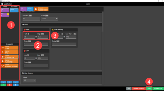
Setting a High Coolant Limit
To set a High Coolant Limit use the following steps:
- Specify the operation by selecting the tool, section, and channel from the lists on the left side of the Job Editor. The selected operation is displayed at the top of the Job Editor.
- In the Limits section of the Job Editor, click the High Limit % field
- Enter the percentage above the learned coolant flow/pressure that will trigger a High alarm condition.
- Click Save
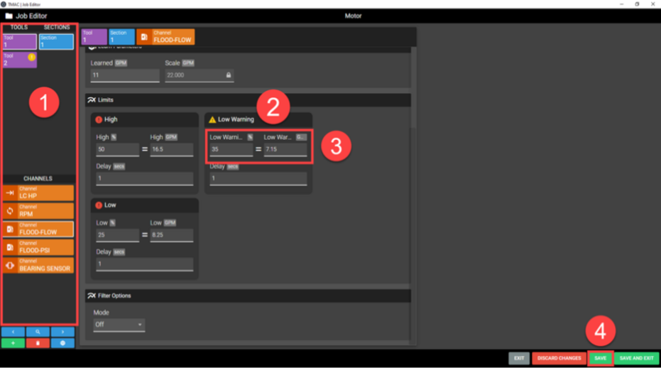
Setting a Low Warning Coolant Limit
To set a Low Warning Coolant limit, use the following steps:
- Specify the operation by selecting the tool, section, and channel from the lists on the left side of the Job Editor. The selected operation is displayed at the top of the Job Editor.
- In the Limits section of the Job Editor, click the Low Warning Limit % field
- Enter the percentage below the Learned Coolant Flow/Pressure that will trigger a Low Warning alarm condition.
- Click Save
Setting a Low Coolant Limit
To set a low coolant limit use the following steps:
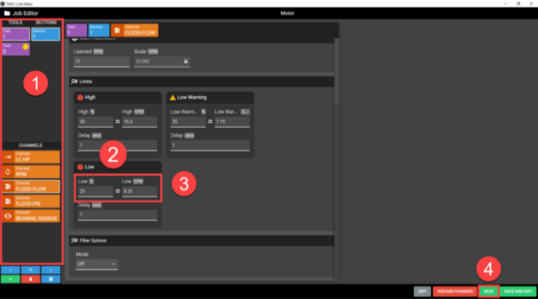
- Specify the operation by selecting the tool, section, and channel from the lists on the left side of the Job Editor. The selected operation is displayed at the top of the Job Editor.
- In the Limits section of the Job Editor, click the Low Limit % field
- Enter the percentage below the Learned Coolant Flow/Pressure that will trigger a Low alarm condition.
- Click SAVE.
Coolant Alarm Delay
The Coolant Alarm Delay specifies a period of time which the measured coolant flow/pressure may exceed (High) or fall below (Low Warning and Low) the programmed limits before triggering an alarm condition.
Setting Coolant Alarm Delay
In the Job Editor:
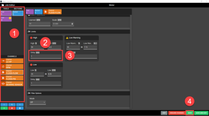
- Specify the operation by selecting the tool, section, and channel from the lists on the left side of the Job Editor. The selected operation is displayed at the top of the Job Editor.
- In the Limits section of the Job Editor, Click the Delay field for the desired limit
- Enter the time in seconds for the alarm delay
- Allowable values range from 0.1 to 320 seconds in 0.1 second increments
- Enter 0.0 to disable the coolant alarm delay
- Click Save
- Repeat steps 2-4 for each limit that requires a delay
Extreme Feedrate Limit
The Extreme Feedrate limit is used to monitor excessive tool wear or breakage in adaptive control. In an adaptive operation, the commanded feedrate is inversely proportional to the signal value. As the signal value increases, TMAC reduces the feedrate to maintain a constant target signal value. When the feedrate over- ride falls below the programmed Extreme Feedrate Limit for the time specified by the Extreme Feedrate Alarm Delay, TMAC triggers an extreme feedrate alarm. The Extreme Feedrate Limit function cannot be disabled. The default value is 20%.
Setting the Extreme Feedrate Limit
In the Job Editor:
- Specify the operation by selecting the tool, section, and channel from the lists on the left side of the Job Editor. The selected operation is displayed at the top of the Job Editor.
- In the segment features section click the Adaptive check-box
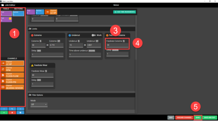
- In the Limits section of the Job Editor, click the Feedrate Extreme % field
- Enter the percentage feedrate that will trigger an Extreme Feedrate Alarm condition.
- Allowable values range from 1% to the max feedrate of the machine
- Must be less than Wear Feedrate % Limit
- Click Save
Extreme Feedrate Alarm Delay
The Extreme Feedrate Delay specifies a time period during which the feedrate can fall below the Extreme Feedrate Limit without triggering an alarm.
Setting an Extreme Feedrate Alarm Delay
In the Job Editor:
- Specify the operation by selecting the tool, section, and channel from the lists on the left side of the Job Editor. The selected operation is displayed at the top of the Job Editor.
- In the Feedrate Extreme Limit section of the Job Editor, click the Delay field
- Enter the duration of the feedrate extreme delay
- Allowable values range from 0.1 to 320 seconds in 0.1 second increments
- Entering a value of 0 disables the Feedrate Extreme alarm delay
- Click SAVE
Wear Feedrate Limit
The Wear Feedrate Limit is used to monitor tool wear in adaptive control. Adapt- ive control determines tool wear by controlling the feedrate override. In an adapt- ive operation, the commanded feedrate is inversely proportional to the signal value. As the signal value increases, TMAC reduces the feedrate to maintain a constant target signal value. When the feedrate override falls below the wear feedrate limit for the time specified by the Wear Feedrate Alarm Delay, TMAC triggers a wear feedrate alarm.
Setting a Wear Feedrate Limit
In the Job Editor:
- Specify the operation by selecting the tool, section, and channel from the lists on the left side of the Job Editor. The selected operation is displayed at the top of the Job Editor.
- In the features section click the Adaptive check-box
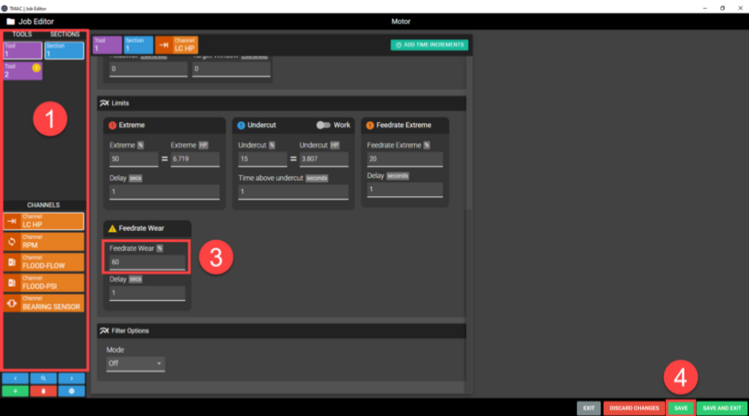
- In the Limits section of the Job Editor, click the Feedrate Wear Limit % field
- Enter the percentage feedrate that will trigger a Wear Feedrate alarm condition.
- Allowable values range from 1% to the max feedrate of the machine
- Must be greater than Extreme feedrate limit
- Click SAVE
Note: Use trial and error to determine the best setting. Remember, the lower the programmed wear feedrate, the longer the tool will cut before generating a wear feedrate alarm.
Wear Feedrate Alarm Delay
The Wear Feedrate Alarm Delay can prevent an instantaneous signal spike and associated feedrate drop from triggering the wear feedrate alarm. These spikes may occur if the tool encounters a hard spot in the material and may not necessarily indicate tool wear. This delay allows the feedrate to drop below the wear feedrate without generating an alarm for the time specified . The Data Viewer can help determine the duration of the spike, and the appropriate value for this delay.
Setting a Wear Feedrate Alarm Delay
In the Job Editor:
- Specify the operation by selecting the tool, section, and channel from the lists on the left side of the Job Editor. The selected operation is displayed at the top of the Job Editor.
- In the Feedrate Wear Limit section of the Job Editor, click the Delay field Enter the duration of the Feedrate Wear delay
- Allowable values range from 0.1 to 320 seconds in 0.1 second increments
- Entering a value of 0 disables the feedrate Wear alarm delay
- Click SAVE
Slope Limit
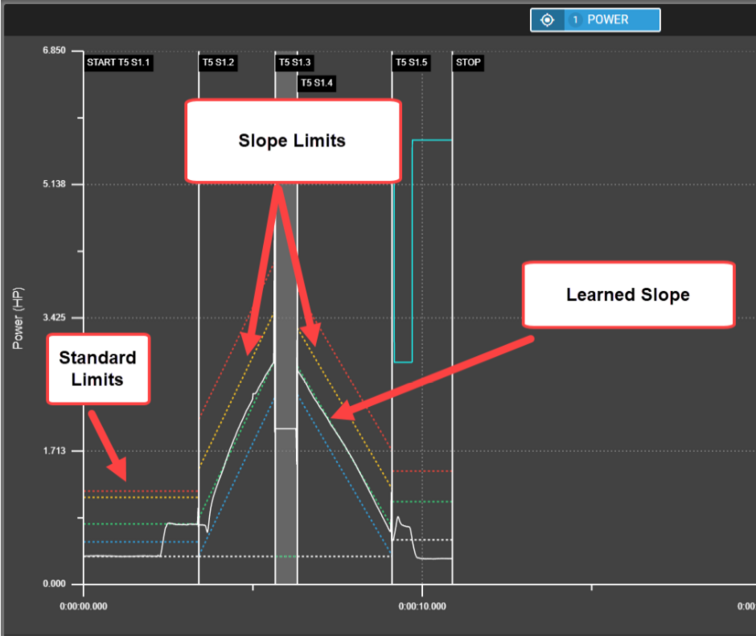
Slope limits are available for operations that employ time increments. Some complex machining operations, such as constant surface speed lathe operations, can be monitored more accurately with slope limits. An operation where the load increases or decreases from start to finish is not accurately monitored with horizontal limits. Slope limits that parallel the slope of the signal value permit more accurate and sensitive monitoring. The following is true when implementing slope limits:
- The operation must employ time increments
- The last time increment in an operation cannot have a slope limit
- Slope parameters define the learned slope value for the operation
- Slope limits are calculated as a percentage above or below the learned slope
Setting Slope Limits
Use the following steps to set slope limits for an operation:
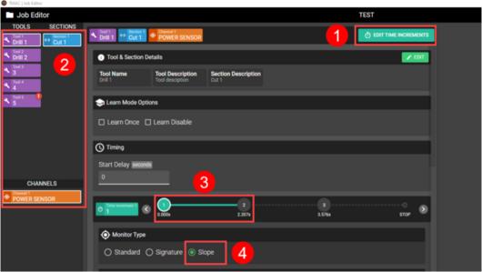
- If the operation does not employ time increments, use the Time Increment Editor to add time increments to the associated operation.
- Specify the operation by selecting the tool, section, and channel from the lists on the left side of the Job Editor. The selected operation is displayed at the top of the Job Editor.
- Select the time increment that requires slope limits
- Select the Slope monitor type
- Enter the Slope parameters:
- Slope Start: Defines the learn value at the start of the time increment
- Slope End: Defines the learn value at the end of the time increment
- Limit Sensitivity: Determines the slope of the slope limits; Increasing the value of this setting makes less parallel to the learned slope, allowing the user to fine tune slope limits
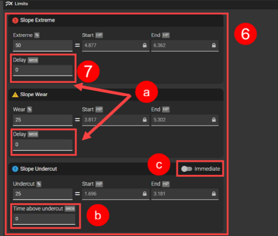
- Set desired limits
- Slope Extreme: Set as a percentage above the learned slope; An alarm is triggered when the signal value exceeds the limit.
- Slope Wear: Set as a percentage above the learned slope; An alarm is triggered when the signal value exceeds the limit.
- Slope Undercut: Set as a percentage below the learned slope; An alarm is triggered if the signal value fails to exceed the limit.
- Set any desired alarm delays
- If an alarm delay is set for slope extreme or wear, an alarm is triggered when the signal value exceeds the limit for the amount of time set in the delay.
- If the Time Above Undercut is set, the signal value must exceed the undercut limit for the amount of time set.
- If the Immediate switch is toggled, the functionality of the Undercut limit changes; An alarm is triggered when the signal value falls below the undercut limit.
Slope Sensitivity Examples
Slope Sensitivity allows the user to fine-tune the behavior of slope limits. Slope limits without limit sensitivity set run parallel to the learned slope value. Increasing the sensitivity causes the limit to be calculated from learned load data samples across the entire time increment. This makes the limits proportional to the learned slope, so that at lower load values in the slope the limits are closer to the learned load limit. Slope limit sensitivity impacts wear and extreme slope limits. If the Immediate switch is toggled for the undercut slope limit, the limit sensitivity will also impact the undercut limit. This is displayed in the following examples:
Signature Limits
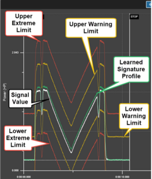
Signature limits offer an alternative to standard monitoring limits. When using standard monitoring limits, the sensor signal is measured against a set value as a percentage above or below the learned peak value. Signature limits are based on a learned signature profile. TMAC accesses the learned profile to build limits that mirror the monitored operation. Alarms are triggered when the sensor signal deviates from the learned profile by the value set for the limit. The following signature limits are available:
- Upper Extreme: When the sensor signal exceeds the learned profile by the value set for the limit, a critical alarm is triggered.
- Upper Warning: When the sensor signal exceeds the learned profile by the value set for the limit, a warning alarm is triggered.
- Lower Warning: When the sensor signal falls below the learned profile by the value set for the limit, a warning alarm is triggered.
- Lower Extreme: When the sensor signal falls below the learned profile by the value set for the limit, a critical alarm is triggered.
Setting Signature Limits
Use the following steps to set signature limits for an operation:
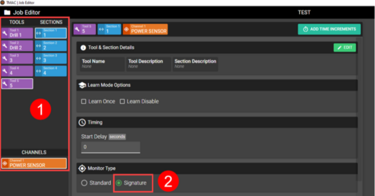
- Specify the operation by selecting the tool, section, channel and time increment (optional) from the lists on the left side of the Job Editor. The selected operation is displayed at the top of the Job Editor.
- Select the signature monitor type.
- Note: When selecting the signature monitor type, the operation should be re-learned using the Learn Once feature
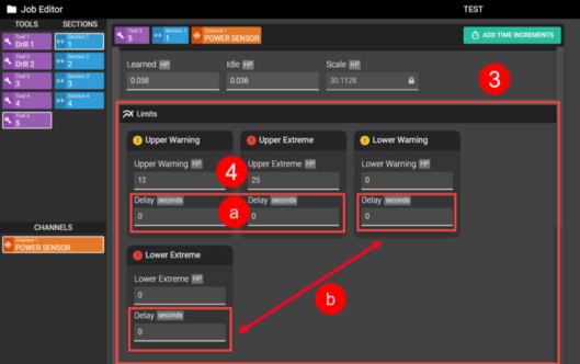
- Set desired limits:
- Upper Extreme: Set as a value above the learned profile; A critical alarm is triggered when the signal value exceeds the limit.
- Upper Warning: Set as a value above the learned profile; A warning alarm is triggered when the signal value exceeds the limit.
- Lower Warning: Set as a value below the learned profile; A warning alarm is triggered when the signal value falls below the limit.
- Lower Extreme: Set as a value below the learned profile; A critical alarm is triggered when the signal value falls below the limit.
- Set any desired alarm delays
- If an alarm delay is set for the upper extreme or upper warning lim- its, an alarm is triggered when the signal value exceeds the limit for the amount of time set in the delay
- If an alarm delay is set for the lower extreme or lower warning lim- its, an alarm is triggered when the signal value falls below the limit for the amount of time set in the delay


