| Line 300: | Line 300: | ||
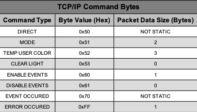
[[File:Screen Shot 2022-09-28 at 12.59.43 PM.png|center|thumb|USB Command Bytes]] | [[File:Screen Shot 2022-09-28 at 12.59.43 PM.png|center|thumb|USB Command Bytes]] | ||
=== '''Mode Set''' === | |||
The mode command is much like the RS232 protocol which allows setting a mode configured in the recipe file to the light stack. The mode value is the only data parameter the should be included in the packet. The mode number is 16 bit integer split up into two separate bytes (little endian). The USB packet must have the following packet data format when sending a direct set segment mode command to the system: | The mode command is much like the RS232 protocol which allows setting a mode configured in the recipe file to the light stack. The mode value is the only data parameter the should be included in the packet. The mode number is 16 bit integer split up into two separate bytes (little endian). The USB packet must have the following packet data format when sending a direct set segment mode command to the system: | ||
| Line 312: | Line 312: | ||
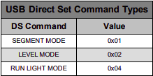
The available direct set command types are listed below: | The available direct set command types are listed below: | ||
[[File:Screen Shot 2022-09-28 at 1.07.16 PM.png|center|thumb|Direct Set Command Types]] | |||
===== '''Direct Set - Segment Mode''' ===== | |||
The usb packet must have the following packet data format when sending a direct set segment mode command to the system: | |||
* Byte[0] = Identification byte | |||
* Byte[1] = 0x50 (direct set) | |||
* Byte[2] = 0x01 (segment mode) | |||
* Byte[3] = Segment Count (1-5) | |||
* Byte[4] = Segment 1 Color | |||
* Byte[5] = Segment 1 Type ... | |||
* Byte[X] = Segment X Color | |||
* Byte[X+1] = Segment X Type | |||
* Byte[X+2] = Blink Frequency | |||
* Byte[X+3] = Buzzer Type | |||
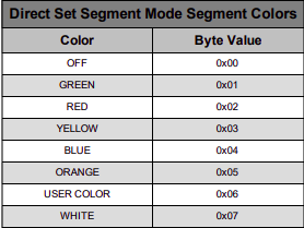
The table below displays all of the available segment colors: | |||
[[File:Screen Shot 2022-09-28 at 1.13.28 PM.png|center|thumb|Segment Colors (Direct Set Segment Mode)]] | |||
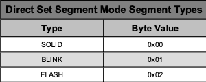
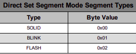
The table below displays all of the available segment types: | |||
[[File:Screen Shot 2022-09-28 at 1.14.27 PM.png|center|thumb|Segment Types (Direct Set Segment Mode)]] | |||
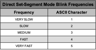
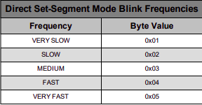
The table below displays all available blink frequencies: | |||
[[File:Screen Shot 2022-09-28 at 1.21.48 PM.png|center|thumb|Blink Frequencies (Direct Set Segment Mode)]] | |||
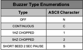
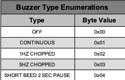
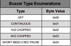
The table displays all available buzzer states: | |||
[[File:Screen Shot 2022-09-28 at 1.22.57 PM.png|center|thumb|Buzzer Enumerations(Direct Set Segment Mode)]] | |||
===== '''Direct Set - Level Mode''' ===== | |||
The usb packet must have the following packet data format when sending a direct set level mode command to the system: | |||
* Byte[0] = Identification byte | |||
* Byte[1] = 0x50 (direct set) | |||
* Byte[2] = 0x02 (level mode) | |||
* Byte[3] = Level Type | |||
* Byte[4] = Level Color | |||
* Byte[5] = Level Value (light count 0-20) | |||
* Byte[6] = Buzzer Type | |||
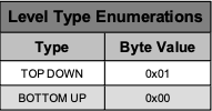
The table below displays all available level types: | |||
[[File:Screen Shot 2022-09-28 at 1.27.13 PM.png|center|thumb|Level Type Enumerations]] | |||
Revision as of 13:29, 28 September 2022
Back to Smart Light Categories Page
The Smart Light hardware is capable of communicating to devices using several protocols. Through these protocols the light can be set directly and modes can be triggered. The following protocols can be used with Smart Light:
- RS232
- TCP/IP
- USB (libusb-1.0)
- 24V 8 bit I/O
How to use these protocols to trigger modes and direct set the light is explained in the following sections.
RS232 Protocols
The RS232 protocol for triggering a modes and direct setting the light is much like the other RS232 protocols written by Caron Engineering. Each packet requires a start of packet, mode command, and end an end of packet. The start of packet and end of packet are built from the single character delimiter configured in the recipe file.
The RS232 protocol is currently uni-directional (Only receives data). The serial strings are in ASCII format and must have the following format when sending a command to the system:
(Delimiter)(Delimiter)(Delimiter)(Delimiter)(Delimiter)(Command Letter)(Param1)(Param2)...(ParamX)(Delimiter)(Delimiter)
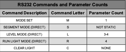
All available command letters are shown in the table below:
Mode Set
The mode set command allows changing the light with respect to the configured modes within the recipe. The mode set command lay- out is as follows:
(Delimiter)(Delimiter)(Delimiter)(Delimiter)(Delimiter)(M)(Mode#) (Delimiter)(Delimiter)
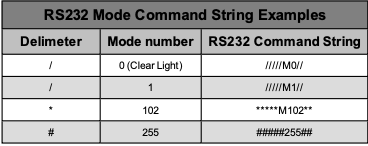
A table of examples is shown below:
Segment Mode (Direct)
The segment mode direct command allows changing the light to segment mode directly. The segment mode command layout is as follows:
(Delimiter)(Delimiter)(Delimiter)(Delimiter)(Delimiter)(S)(Segment Count)(Segment 1 Color)(Segment 1 Type)(Segment 2 Color)(Seg- ment 2 Type)...(Segment X Color)(Segment X Type)(Blink Frequency)(Buzzer Type)(Delimiter)(Delimiter)
The amount of parameters vary with respect to the segment count. If the segment count is only equal to 1, then only 1 segment color and 1 segment type should be defined. For example, if the segment count is set to 2, the following structure should be used:
(Delimiter)(Delimiter)(Delimiter)(Delimiter)(Delimiter)(S)(Segment Count)(Segment 1 Color)(Segment 1 Type)(Segment 2 Color)(Seg- ment 2 Type)(Blink Frequency)(Buzzer Type)(Delimiter)(Delimiter)
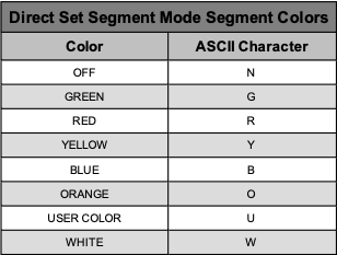
The segment colors are represented as a single ascii character.
Level Mode (Direct)
The level mode direct command allows changing the light to level mode directly. The level mode command layout is as follows:
(Delimiter)(Delimiter)(Delimiter)(Delimiter)(Delimiter)(L)(Level Type)(Level Color)(Level Light Count Digit 1)(Level Light Count Digit 2)(Buzzer Type)(Delimiter)(Delimiter)
The light color is a 2 digit number (0-20 lights). If the light count is less than 20, then a leading 0 character is required before the single digit number to keep the ascii representation as 2 characters.
The level types are represented as a single ascii character displays all available level types:
Run Light (Direct)
The run light mode direct command allows changing the light to run light mode directly. The run light mode command layout is as follows:
(Delimiter)(Delimiter)(Delimiter)(Delimiter)(Delimiter)(R)(Run Segment Count)(Run Color)(Back Color)(Run Speed)(Buzzer Type) (Delimiter)(Delimiter)
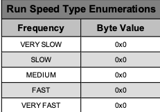
The run speeds are represented as a single ascii character.
Temporary User Color
The temporary user color command is represented as 3 separate hex values for the complete RGB spectrum. Each hex value can be from a value from 0-255 in hex (00 to FF). A table of examples is shown below:
Clear Light
This command is the same as sending a mode set with a mode number of 0.
TCP/IP Protocol
The TCP/IP protocol allows for triggering modes, directly setting the lights, and getting status updates when a mode has changed.
Packet Structure
The packet structure for a complete tcp datagram is split up into two different parts, a packet header, and the packet data. Each datagram sent to the device will automatically be returned with a datagram containing the status of the command. If the command byte sent is equal to the command byte in the reply packet, then the packet was considered successful. If an invalid tcp datagram is been sent to the device, the connection will be closed immediately from the host. All packet data is packed in little endian format.
The server port number is 13000.
Packet Header
The packet header contains the following 3 bytes:
- Byte 1 (Identification Byte): Gets returned in the reply data- gram for packet ordering
- Byte 2 (Packet Length): Complete size of the datagram
- Byte 3 (Command Byte): Command byte associated with the packet data
The packet header is used with the command tcp datagram and the reply tcp datagram.
Packet Data
The packet data size is dependent on the command byte sent. In a command packet, the data is associated with the command. In a reply packet, the data is associated with the error code returned.
Command Bytes
Mode Set
The mode command is much like the RS232 protocol which allows setting a mode configured in the recipe file to the light stack. The mode value is the only data parameter the should be included in the datagram.
The mode number is 16 bit integer split up into two separate bytes (little endian). An example of a command that sets mode 255 is as follows:
- Byte[0] = 0x01 (identification byte)
- Byte[1] = 0x05 (packet size)
- Byte[2] = 0x51 (command byte)
- Byte[3] = 0x00 (MSB)
- Byte[4] = 0xFF (LSB)
Direct Set
The direct set command allows direct access to the light stack. The TCP/IP datagram data size vary with respect to the direct set command type being sent.
The available direct set command types are listed below:
Direct Set - Segment Mode
The TCP/IP datagram must have the following packet data format when sending a direct set segment mode command to the system:
- Byte[0] = 0x01 (identification byte)
- Byte[1] = 7 + (2 * Segment Count) (packet size)
- Byte[2] = 0x50 (direct set)
- Byte[3] = 0x01 (segment mode)
- Byte[4] = Segment Count (1-5)
- Byte[5] = Segment 1 Color
- Byte[6] = Segment 1 Type
- ...
- Byte[X] = Segment X Color
- Byte[X+1] = Segment X Type
- Byte[X+2] = Blink Frequency
- Byte[X+3] = Buzzer Type
The packet size is dependent on the desired segment count while in segment mode. The formula for calculating the packet size is the following:
PACKET_SIZE = 7 + (2 * SEGMENT_COUNT)
Direct Set - Level Mode
The TCP/IP datagram must have the following packet data format when sending a direct set level mode command to the system:
- Byte[0] = 0x01 (Identification byte)
- Byte[1] = 0x08 (packet size)
- Byte[2] = 0x50 (direct set)
- Byte[3] = 0x02 (level mode)
- Byte[4] = Level Type
- Byte[5] = Level Color
- Byte[6] = Level Value (light count 0-20)
- Byte[7] = Buzzer Type
Direct Set - Run Light Mode
The TCP/IP datagram must have the following packet data format when sending a direct set run light mode command to the system:
- Byte[0] = 0x01 (Identification byte)
- Byte[1] = 0x09
- Byte[2] = 0x50 (direct set)
- Byte[3] = 0x02 (run light mode)
- Byte[4] = Segment Count (1-3)
- Byte[5] = Run Color
- Byte[6] = Back Color
- Byte[7] = Run Speed
- Byte[8] = Buzzer Type
Temporary User Color
The TCP/IP datagram must have the following packet data format when sending a direct set Temporary User Color command to the system:
- Byte[0] = Identification byte
- Byte[1] = 0x06
- Byte[2] = 0x52 (user color)
- Byte[3] = RED (in hex)
- Byte[4] = GREEN (in hex)
- Byte[5] = BLUE (in hex)
Bytes 3, 4, and 5 are the corresponding RGB values for the full RGB color spectrum.
Clear Light
This command is the same as sending a mode set with a mode number of 0.
Enable Events
The TCP/IP datagram must have the following packet data format when sending an enable events command to the system:
- Byte[0] = 0x01 (identification byte)
- Byte[1] = 0x04
- Byte[2] = 0x60 (enable events)
- Byte[3] = Identification byte for events
When this command is sent to the device and a successful reply is returned, all mode set and light changes will be sent to the connected client. This enabled tracking of what modes or light contents are active or have been previously active on the light stack. The value of byte 3 will be send in every event occurred packet as its identification byte. By default, all events are disable upon connection and will be disabled upon disconnection.
Disable Events
The TCP/IP datagram must have the following packet data format when sending a disable events command to the system:
- Byte[0] = 0x01 (identification byte)
- Byte[1] = 0x03
- Byte[2] = 0x61 (disable events)
When this command is sent to the device and a successful reply is returned, all mode set and light change events will be disabled (must have previously sent an enable events command). This is the default one once a client connects to the device server.
Event Occurred
The event occurred datagram packet is a one directional datagram command that is sent from the device server to the client. This packet will occur when events have been enabled on the device server, and a mode set / light change occurs. TCP/IP datagram will have the following packet data format:
- Byte[0] = 0xXX (identification byte from enable events command)
- Byte[1] = 0xXX (depends on the event type)
- Byte[2] = 0x61 (event occurred)
- Byte[3] = Event Type
- Byte[4] = Event Data[0]
- Byte[5] = Event Data[1]
- …
- Byte[X] = Event Data[X]
Below is a table of all event types:
All event data is the same as the set commands.
Example 1:
If mode 255 was set on the light, events were enabled and 0x20 was set as the enable events identification byte; the following packet would be received:
- Byte[0] = 0x20 (identification byte from enable events command)
- Byte[1] = 0x06
- Byte[2] = 0x61 (event occurred)
- Byte[3] = 0x51 (mode set)
- Byte[4] = 0x00 (MSB)
- Byte[5] = 0xFF (LSB)
Example 2:
If direct set segment mode was set on the light (1 segment, green, solid, no buzzer) and events were enabled and 0x50 was set as the enable events identification byte; the following packet would be received:
- Byte[0] = 0x50 (identification byte from enable events command)
- Byte[1] = 0x09
- Byte[2] = 0x61 (event occurred)
- Byte[3] = 0x50 (direct set)
- Byte[4] = 0x01 (segment type)
- Byte[5] = 0x01 (segment count)
- Byte[6] = 0x01 (segment 1 green)
- Byte[7] = 0x00 (segment 1 solid) Byte[8] = 0x01 (blink flash frequency required…dummy value)
- Byte[8] = 0x00 (no buzzer)
Get Light Status
The TCP/IP datagram must have the following packet data format when sending a get light stats command to the system:
- Byte[0] = 0x01 (Identification byte)
- Byte[1] = 0x03
- Byte[2] = 0x54 (get light status)
The get light status command is an alternative polling method to get the light status instead of using the event based datagram stream. The return TCP/IP datagram will have the following format:
- Byte[0] = Identification byte
- Byte[1] = Dependent on mode number
- Byte[2] = 0x54 (command echo)
- Byte[3] = MSB of mode number
- Byte[4] = LSB of mode number … (data portion dependent on mode number)
- Byte[X] = Data byte 1
- Byte[X+1] = Data byte 2
The data portion of the packet is dependent on the mode number returned. If the mode number is equal to -1, then the data portion is the direct set contents. The direct set contents are identical to send configuration for a direct set command. If the mode number is greater than or equal to 0, then there is no data portion to the packet (just the mode number is returned).
Error Occurred
The error occurred datagram packet is a uni-directional datagram command that is sent from the device server to the client when an invalid command datagram has been sent to the device. Once this datagram is sent to the client, the connection will be immediately closed (considered fatal error). TCP/IP datagram will have the following packet data format:
- Byte[0] = 0x01 (identification byte from invalid packet)
- Byte[1] = 0x04
- Byte[2] = 0xFF (error occurred)
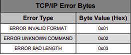
- Byte[3] = Error Type
All available error types are shown in the table below:
USB Protocol (libusb - 1.0)
The usb protocol using libusb-1.0 allows for triggering modes, directly setting the lights, and getting the status of the light using polling. The libusb-1.0 libraries are required for usb communications.
Packet Structure
The packet structure for a complete usb transaction is split up into two different parts, a packet header, and the packet data. Each datagram sent to the device will automatically be returned with a datagram containing the status of the command. If the command byte sent is equal to the command byte in the reply packet, then the packet was considered successful. All invalid packets will be returned with and error message. All packet data is packed in little endian format.
Packet Header
The packet header contains the following 2 bytes:
- Byte 1 (Identification Byte): Gets returned in the reply datagram for packet ordering
- Byte 2 (Command Byte): Command byte associated with the packet data
The packet header is used with the command packet and the reply packet.
Packet Data
The packet data size is dependent on the command byte sent. In a command packet, the data is associated with the command. In a reply packet, the data is associated with the error code returned.
libusb-1.0 Device Defines
All of the IO-Link Controller devices defines are listed below:
- Vendor ID: 0xABCD
- Product ID: 0X0013
- Packet Data In End Point: 0x81
- Packet Data Out End Point: 0x01
A maximum of 512 bytes can be sent at a time while using USB 2.0. Alternatively, a maximum of 64 bytes can be send and received at a time while using USB 1.0.
Command Bytes
The available command types are listed below:
Mode Set
The mode command is much like the RS232 protocol which allows setting a mode configured in the recipe file to the light stack. The mode value is the only data parameter the should be included in the packet. The mode number is 16 bit integer split up into two separate bytes (little endian). The USB packet must have the following packet data format when sending a direct set segment mode command to the system:
- Byte[0] = Identification byte
- Byte[1] = 0x51 (command byte)
- Byte[2] = MSB of mode
- Byte[3] = LSB of mode
Direct Set
The direct set command allows direct access to the light stack. The usb packet data size vary size vary with respect to the direct set command type being sent.
The available direct set command types are listed below:
Direct Set - Segment Mode
The usb packet must have the following packet data format when sending a direct set segment mode command to the system:
- Byte[0] = Identification byte
- Byte[1] = 0x50 (direct set)
- Byte[2] = 0x01 (segment mode)
- Byte[3] = Segment Count (1-5)
- Byte[4] = Segment 1 Color
- Byte[5] = Segment 1 Type ...
- Byte[X] = Segment X Color
- Byte[X+1] = Segment X Type
- Byte[X+2] = Blink Frequency
- Byte[X+3] = Buzzer Type
The table below displays all of the available segment colors:
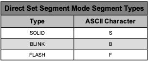
The table below displays all of the available segment types:
The table below displays all available blink frequencies:
The table displays all available buzzer states:
Direct Set - Level Mode
The usb packet must have the following packet data format when sending a direct set level mode command to the system:
- Byte[0] = Identification byte
- Byte[1] = 0x50 (direct set)
- Byte[2] = 0x02 (level mode)
- Byte[3] = Level Type
- Byte[4] = Level Color
- Byte[5] = Level Value (light count 0-20)
- Byte[6] = Buzzer Type
The table below displays all available level types:
