Back to MiConnect Categories Page
The Routine Diagram is where Tool Connect routines are built and managed. The interface provides functionality to manage routines, create and edit routine steps, and to add operation blocks to develop grunting flow.
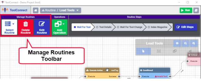
Manage Routines Tool Bar
The Manage Routines tool bar offers the following functionality
- Select Routine: Opens a menu containing a list of already created routines. Additionally a new routine can be created using the New Routine button.
- Delete Routine: Pressing the Delete Routine button deletes the currently loaded routine.
- Edit Routine: The Edit Routine button allows the details of the currently loaded routine to be modified.
Edit Routine Details
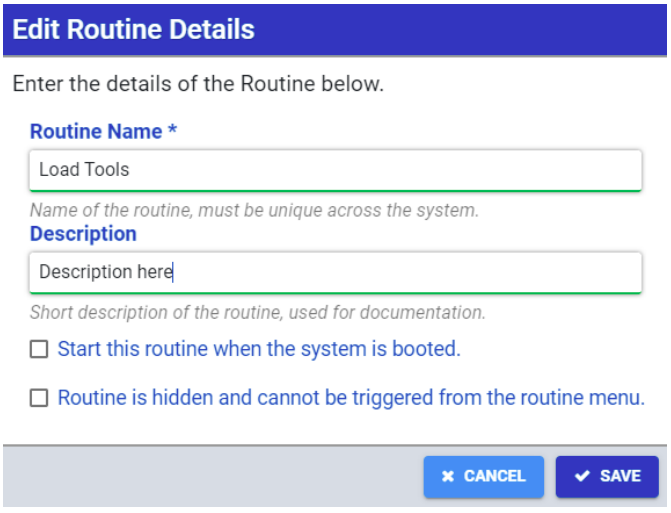
The routine details are as follows:
- Routine Name: This is the name of the routine as it is displayed in Tool Connect. This must be a unique name across the system.
- Description: Enter a description for the routine. This appears in automatically generated system documentation.
- Start this routine when the system is booted: When enabled, the routine will start on system startup
- Routine is hidden and cannot be triggered from the routine menu: When enabled, the routine does not appear in the routine list of the main menu.
Routine Steps
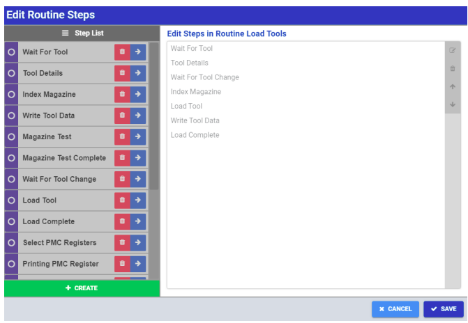
Routine steps are the building blocks of a routine process. Each step has its own grid where operation blocks can be added. The routine steps for the currently loaded routine are displayed at the top of the routine editor. Clicking on an individual routine step loads that step in the routine diagram. The Edit Steps button is used to add, remove, create and reorder steps in the routine.
Note: Routine steps are global to the project and can be reused in multiple routines.
Operations
The Add Operations button opens a menu with all Tool Connect operations available to the system. Additional operation sets are available depending on the various plug-ins that have been configured for the system. Operations are visually represented on the routine diagram by the individual blocks in a routine step.
Tool Connect Operation Set
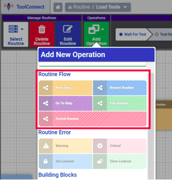
Routine Flow
Routine Flow operation blocks affect transitions between routine steps and other routines. The following routine flow operations are available:
- Next Step - When executed Tool Connect transitions to the next step in the routine
- Restart Routine - Returns the routine to the starting block of the first step in the current routine
- Go To Step - Transitions to a specific routine step in the current routine
- End Routine - Ends the routine and returns tool connect to the main menu where routines can be selected
- Switch Routine - Transitions to the first step in a different routine
Routine Error
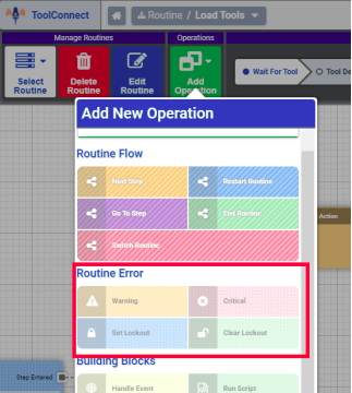
Routine Error operation blocks provide a means to trigger error responses during a routine. The following routine error operations are available:
- Warning - Issues a warning error (yellow) on the main interface, if the specified condition occurs.
- Critical - Issues a critical error (red) on the main interface, if the specified condition occurs.
- Set Lockout - This error operation block returns Tool Connect to the run-time menu and prevents any actions until the lockout is cleared.
- Clear Lockout - This error operation ends the lockout condition triggered by the set lockout operation block
For the warning and critical error operation blocks, an additional error action may be specified after the error occurs. The following actions are available
- End Routine - Ends the currently loaded routine
- Restart Routine - Returns to the starting block of the first step of the currently loaded routine
- Go to step - Goes to the starting block of a specified step in the routine
- Continue - Continues the routine flow into the next operation block
Note: If a Timeout is set for the error, the error clears after the specified amount of time. Additionally, a timeout action may be specified and the options are the same as the error actions listed above
Building Blocks
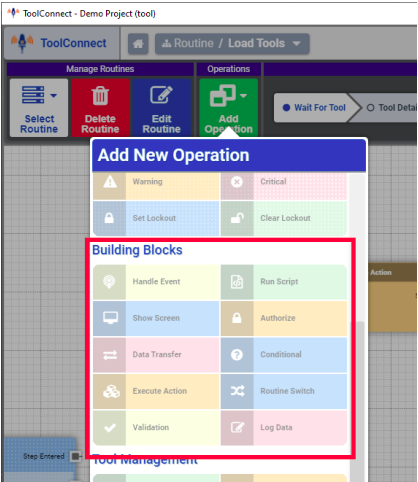
Building block operation blocks interact with the system api and other system components to provide and handle system actions and events.
- Handle Event: Triggers a response when a specified event occurs
- Run Script: Runs a predefined typescript/javascript to perform more advanced operations
- Show Screen: Overlays a customized screen on the main interface
- Authorize: Validates that the current user has a specific roles and may authorize additional roles on a one time basis.
- Data Transfer: Initiates a data transfer between two components in the system
- Conditional: Performs conditional logic on data using expressions.
- Execute Action: Executes a specified action from any system component
- Routine Switch: Executes a switch statement that acts as a conditional by interrogating the active routine. This allows a specific action to be taken based on the current routine.
- Validation: This operations validates data using expressions l Log Data: Amends specified data in the system logger
Tool Management
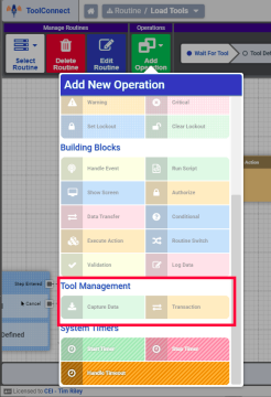
Tool management operations handle Tool data transactions. Tool data transactions can be tracked and managed internally or can be pulled from compatible CNC machines. The following operations are available:
- Capture Data: Captures tool data transactions from specified sources. The sources can be internal or from a compatible external source
- Transaction: Runs a preconfigured tool transaction. This is defined in the Tool management utility
System Timers
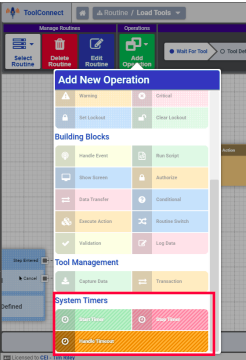
System Timer operation blocks handle ere-configured system timers.
- Start Timer: Starts a predefined system timer
- Stop Timer: Stops a predefined system timer
- Handle Timeout: Determines how the timeout for a specified system timer is handled. When the system timer reaches its timeout, the specified action is taken.
Plugin Operation Sets
Some plugins provide additional operation blocks. The following plugin-based operation blocks are available:
- Read Next Tag (RFID Plugin): Automatically reads tag data from the next tag that is present.
- Wait for Serial Data (Serial Port Plugin): Waits for the next available serial data from the specified port and processes the data automatically.
Note: These plugin based operation blocks are only available when the associated plugin is configured.
