CNC Command Overview
DTect-IT can receive start and stop commands from a CNC for each analysis. If CNC communications are enabled in the CNC settings for an analysis, a Command ID can be programmed. The command ID is an integer value that is used in the CNC command structure to command a DTect-IT analysis to start or stop. Commands must be in the following format:
<Command_ID.Analysis_Command>
Commands are sent through the chosen register set in the CNC Configuration tab in each analysis. A different Command ID can be used for each analysis or a single Command ID can be shared between multiple analysis.
Example 1:
Three analyses have the following programmed Command ID's and Command variables:
In this example, inputting 1.1 into a command variable starts the analysis associated with that command variable.
- Inputting 1.1 in macro variable 110 starts Limit Analysis 1.
- Inputting 1.1 in macro variable 111 starts Bearing Analysis.
- Inputting 1.1 in macro variable 112 starts Limit Analysis 2.
Example 2:
Three analyses have the following programmed Command ID's and Command variables:
In this example, the 3 analyses share a command variable but have different programmed command ID's.
- Inputting 1.1 in macro variable 110 starts Limit Analysis 1.
- Inputting 2.1 in macro variable 110 starts Bearing Analysis.
- Inputting 3.1 in macro variable 110 starts Limit Analysis 2.
Example 3:
Three analyses have the following programmed Command ID's and Command variables:
In this example, the 2 limit analyses share a command variable and command ID. The bearing analysis shares the command variable, but it has a separate command ID.
- Inputting 1.1 in macro variable 110 starts Limit Analysis 1 and 2.
- Inputting 2.1 in macro variable 110 starts Bearing Analysis.
Command Variable Error
The table below shows the command return when invalid commands are issued. For analysis specific variable commands and returns, refer to the CNC Configuration settings for the specific analysis.
Note: Fault Detection does not support CNC start and stop commands. Fault Detection does send data to selected variables programmed in the settings.
Fanuc
DTect-IT is capable of communicating with Fanuc controls using Focas 1 or 2. Create a Fanuc CNC using the Fanuc CNC wizard. The CNC wizard can be accessed in the general settings CNC ribbon or in the CNC tab of the analysis settings.
Fanuc Wizard
The Fanuc CNC wizard eases the setup of a Fanuc CNC device by guiding the user through the settings step by step. To set up a new CNC, press the Create button in the CNC settings menu and select Fanuc. Perform the following steps in the wizard to create the CNC:
- Press Begin.
- Enter the Host Name (or IP Address) and Port number of the Fanuc CNC.
- DTect-IT will attempt to connect to the CNC. After DTect-IT finishes connecting to the CNC, press Continue.
- Enter a CNC path to operate on from the drop down menu.
- Name the CNC and press Finish.
After completing the Fanuc CNC wizard, the Fanuc CNC will be available to be utilized by analyses.
Fanuc Settings
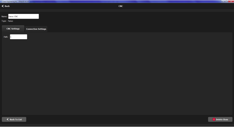
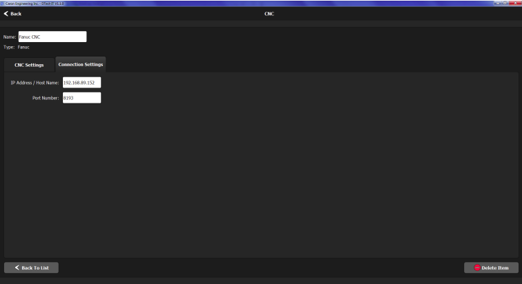
In the Fanuc settings menu, the CNC can be renamed. The Fanuc settings menu has two tabs:
- CNC
- Connection
CNC Tab
In the CNC settings tab, the CNC path DTect-IT operates on can be changed.
Connection Settings Tab
The following settings can be configured in the Connection Settings tab:
- Host Name (or IP Address): Enter the Host Name(or IP Address) of the CNC DTect-IT is communicating with.
- Port Number: Enter the port number of the Fanuc CNC DTect-IT is communicating with. The port number is generally 8193 by default.
Okuma (Server or API)
DTect-IT is capable of communicating with Okuma controls (P200 and P300 controls). Create an Okuma CNC using the Okuma CNC wizard. The CNC wizard can be accessed in the general settings CNC ribbon or in the CNC tab of the analysis settings.
Note: A CEI server must be installed for DTect-IT to communicate with this control. Please contact Caron Engineering for the appropriate documentation.
Okuma Wizard
The Okuma CNC wizard eases the setup of a Okuma CNC device by guiding the user through the settings step by step. To set up a new CNC, press the Create button in the CNC settings menu and select Okuma or Okuma API.
Note: When setting up communications with an Okuma control, DTect-IT can utilize the Okuma server or the Okuma API for communication. The steps in the wizard are the same whether utilizing the server or the API. Perform the following steps in the wizard to create the CNC:
- Press Begin.
- Enter the Host Name (or IP Address) and Port number of the Okuma CNC.
- DTect-IT will attempt to connect to the CNC. After DTect-IT finishes connecting to the CNC, press Continue.
- Enter a CNC subsystem to operate on from the drop down menu.
- Name the CNC and press Finish.
After completing the Okuma CNC wizard, the Okuma CNC will be available to be utilized by analyses
Okuma Settings
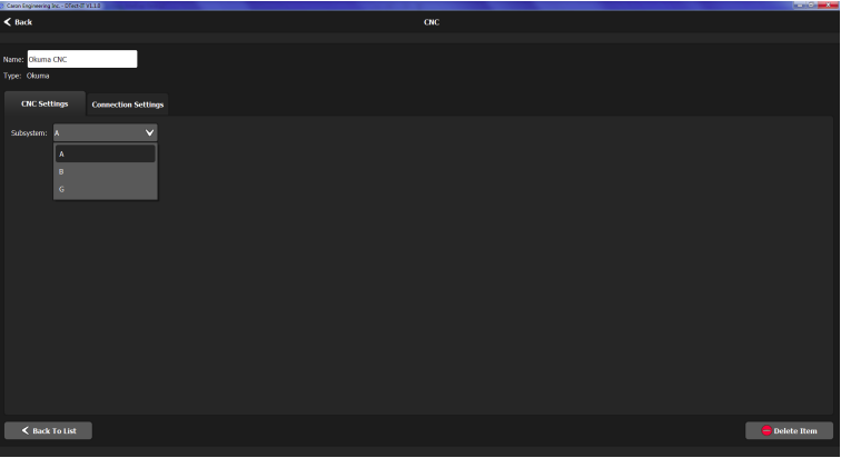
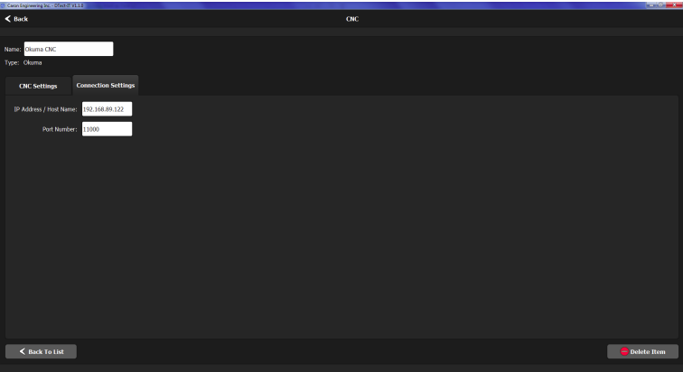
In the Okuma settings menu, the CNC can be renamed. The Okuma settings menu has two tabs:
- CNC
- Connection
CNC Tab
In the CNC settings tab, the CNC subsystem DTect-IT operates on can be changed.
Connection Settings Tab
The following settings can be configured in the Connection Settings tab:
- Host Name (or IP Address): Enter the Host Name(or IP Address) of the CNC DTect-IT is communicating with.
- Port Number: Enter the port number of the CNC DTect-IT is communicating with.
Siemens
DTect-IT is capable of communicating with Siemens controls. Create a Siemens CNC using the Siemens CNC wizard. The CNC wizard can be accessed in the general settings CNC ribbon or in the CNC tab of the analysis settings.
Note: A CEI server must be installed for DTect-IT to communicate with this control. Please contact Caron Engineering for the appropriate documentation.
Siemens Wizard
The Siemens CNC wizard eases the setup of a Siemens CNC device by guiding the user through the settings step by step. To set up a new CNC, press the Create button in the CNC settings menu and select Siemens. Perform the following steps in the wizard to create the CNC:
- Press Begin.
- Enter the Host Name (or IP Address) and Port number of the Siemens CNC.
- DTect-IT will attempt to connect to the CNC. After DTect-IT finishes connecting to the CNC, press Continue.
- Select the NCU (1-4) and Channel (1-10) numbers from the drop down menus.
- Name the CNC and press Finish.
After completing the Siemens CNC wizard, the Siemens CNC will be available to be utilized by analyses.
Siemens Settings
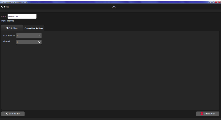
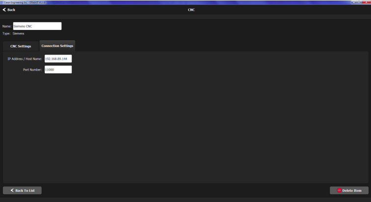
In the Siemens settings menu, the CNC can be renamed. The Siemens settings menu has two tabs:
- CNC
- Connection
CNC Tab
In the CNC settings tab, the NCU and Channel numbers can be changed.
Connection Settings Tab
The following settings can be configured in the Connection Settings tab:
- Host Name (or IP Address): Enter the Host Name(or IP Address) of the CNC DTect-IT is communicating with.
- Port Number: Enter the port number of the CNC DTect-IT is communicating with.
Citizen
DTect-IT is capable of communicating with Citizen controls. Create a Citizen CNC using the Citizen CNC wizard. The CNC wizard can be accessed in the general settings CNC ribbon or in the CNC tab of the analysis settings.
Note: A CEI server must be installed for DTect-IT to communicate with this control. Please contact Caron Engineering for the appropriate documentation.
Citizen Wizard
The Citizen CNC wizard eases the setup of a Citizen CNC device by guiding the user through the settings step by step. To set up a new CNC, press the Create button in the CNC settings menu and select Citizen. Perform the following steps in the wizard to create the CNC:
- Press Begin.
- Enter the Host Name (or IP Address) and Port number of the Citizen CNC.
- DTect-IT will attempt to connect to the CNC. After DTect-IT finishes connecting to the CNC, press Continue.
- Name the CNC and press Finish.
After completing the Citizen CNC wizard, the Citizen CNC will be available to be utilized by analyses.
Citizen Settings
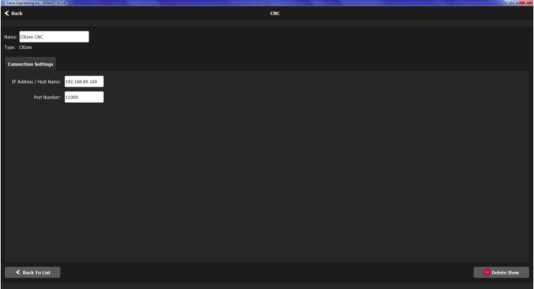
In the Citizen settings menu, the CNC can be renamed. The Citizen settings menu has one tab:
- Connection
Connection Settings Tab
The following settings can be configured in the Connection Settings tab:
- Host Name (or IP Address): Enter the Host Name(or IP Address) of the CNC DTect-IT is communicating with.
- Port Number: Enter the port number of the CNC DTect-IT is communicating with.
Mitsubishi
DTect-IT is capable of communicating with Mitsubishi controls. Create aMitsubishi CNC using the Mitsubishi CNC wizard. The CNC wizard can be accessed in the general settings CNC ribbon or in the CNC tab of the analysis settings.
Note: A CEI server must be installed for DTect-IT to communicate with this control. Please contact Caron Engineering for the appropriate documentation.
Mitsubishi Wizard
The Mitsubishi CNC wizard eases the setup of a Mitsubishi CNC device by guiding the user through the settings step by step. To set up a new CNC, press the Create button in the CNC settings menu and select Mitsubishi. Perform the following steps in the wizard to create the CNC:
- Press Begin.
- Enter the Host Name (or IP Address) and Port number of the Mitsubishi CNC.
- DTect-IT will attempt to connect to the CNC. After DTect-IT finishes connecting to the CNC, press Continue.
- Name the CNC and press Finish.
After completing the Mitsubishi CNC wizard, the Mitsubishi CNC will be available to be utilized by analyses.
Mitsubishi Settings
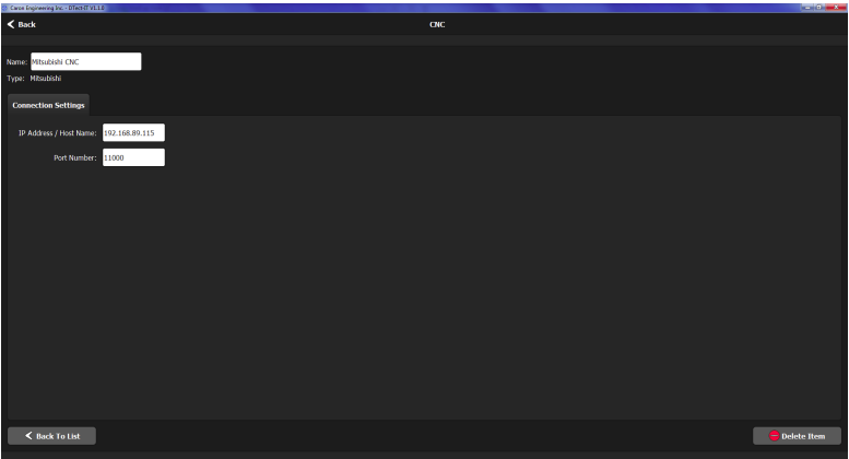
In the Mitsubishi settings menu, the CNC can be renamed. The Mitsubishi settings menu has one tab:
- Connection
CNC Tab
The following settings can be configured in the Connection Settings tab:
- Host Name (or IP Address): Enter the Host Name(or IP Address) of the CNC DTect-IT is communicating with.
- Port Number: Enter the port number of the CNC DTect-IT is communicating with.
Connection Settings Tab
Heidenhain iTNC640
DTect-IT is capable of communicating with Heidenhain iTNC640 controls. Create a Heidenhain iTNC640 CNC using the Heidenhain iTNC640 CNC wizard. The CNC wizard can be accessed in the general settings CNC ribbon or in the CNC tab of the analysis settings.
Note: A CEI server must be installed for DTect-IT to communicate with this control. Please contact Caron Engineering for the appropriate documentation.
Heidenhain Wizard
The Heidenhain iTNC640 CNC wizard eases the setup of a Heidenhain iTNC640 CNC device by guiding the user through the settings step by step. To set up a new CNC, press the Create button in the CNC settings menu and select Heidenhain iTNC640. Perform the following steps in the wizard to create the CNC:
- Press Begin.
- Enter the Host Name (or IP Address) and Port number of the Heidenhain iTNC640 CNC.
- DTect-IT will attempt to connect to the CNC. After DTect-IT finishes connecting to the CNC, press Continue.
- Enter the Heidenhain Channel Number and press Continue
- Name the CNC and press Finish.
After completing the Heidenhain iTNC640 CNC wizard, the Heidenhain iTNC640 CNC will be available to be utilized by analyses.
Heidenhain Settings
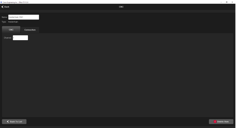
In the Heidenhain iTNC640 settings menu, the CNC can be renamed. The Heidenhain iTNC640 settings menu has two tabs:
- CNC
- Connection
CNC Tab
In the CNC settings tab, the Channel number can be changed.
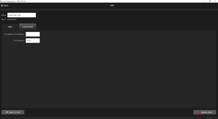
Connection Settings Tab
The following settings can be configured in the Connection Settings tab:
- Host Name (or IP Address): Enter the Host Name(or IP Address) of the CNC DTect-IT is communicating with.
- Port Number: Enter the port number of the CNC DTect-IT is communicating with.
RS232
DTect-IT is capable of establishing communications utilizing RS232 protocol.. Create an RS232 CNC using the RS232 CNC wizard. The CNC wizard can be accessed in the general settings CNC ribbon or in the CNC tab of the analysis settings.
RS232 Wizard
The RS232 wizard eases the setup of RS232 communications by guiding the user through the settings step by step. To set up RS232 communications, press the Create button in the CNC settings menu and select RS232. Perform the following steps in the RS232 wizard to establish RS232 communications:
- Press Begin.
- Select the following for the RS232 connection (these values should match the device settings with which DTect-IT is communicating.), then press Continue:
- Port: The Refresh button is used to refresh the list of available ports
- Baud Rate
- Parity
- Stop Bits
- Data Bits
- Flow Control
- Enter the following information, then press Continue:
- Start Delimiter: Character the begins each command
- End Delimiter: Character the ends each command
- Timeout (ms): Time in milliseconds for a command to expire
- Enter a name for the R232 connection and press Finish
RS232 Settings
In the RS232 settings menu, the CNC can be renamed. The RS232 settings menu has two tabs:
- Connection
- Settings
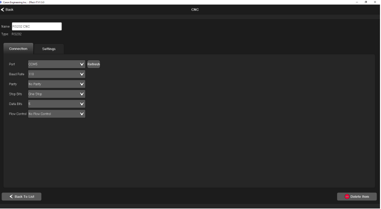
Connection Settings Tab
The following settings can be configured in the Connection tab:
- Port
- Baud Rate
- Parity
- Stop Bits
- Data Bits
- Flow Control
RS232 Settings Tab
The following settings can be configured in the Settings tab:
- Start Delimiter
- End Delimiter
- Timeout (ms)


